
Eureka
For R&D, Eureka makes reading and utilizing patents & technical documents easy.
Eureka AIR
Designed for self-driven R&D workflows. Generate viable solutions, solve complex R&D challenges, empower your innovation with AI.

Eureka Materials
Designed for material experts only. Revolutionize your material R&D, from search, analyze, to developing new materials.

TechResearch
Generate reliable direction feasibility study reports for your R&D in just a few steps.

TechSeek
Discover and master advanced knowledge NOW. Basics, ideas, possibilities, all at once.

TechMind
As an expert in R&D Theories, TechMind can generates customized viable solutions instantly.

TechRisk
Analyze your overall solution with one click, know your potential R&D risks in advance.

TechMonitor
Get weekly tech updates, stay abreast of the latest tech innovations and key insights.
Valve timing mechanism for engine, engine and automobile
A gas distribution mechanism and engine technology, applied in the direction of engine components, machines/engines, mechanical equipment, etc., can solve the problems of low power and emission levels, and achieve the effect of good performance and continuous adjustment
- Summary
- Abstract
- Description
- Claims
- Application Information
AI Technical Summary
Problems solved by technology
Method used
Image

Examples
Embodiment 1
[0030] Embodiment 1 of the present invention provides a gas distribution mechanism for an engine, including a camshaft, a transmission mechanism and a valve, wherein the cam on the camshaft and the transmission mechanism or between the transmission member and the transmission member in the transmission mechanism are arranged There is a slide plate, which has a smooth transition profile; the above-mentioned engine valve mechanism also includes a slide plate control device, which is connected with the slide plate, and is used to control the position of the slide plate between the cam and the transmission mechanism or the position of the slide plate in the transmission The position between the part and the transmission part, and the distance of the transmission mechanism can be changed through the smooth transition of the slide.
[0031] This embodiment is explained by setting a sliding plate between the cam and the transmission mechanism as an example, taking the cam driving the ...
Embodiment 2
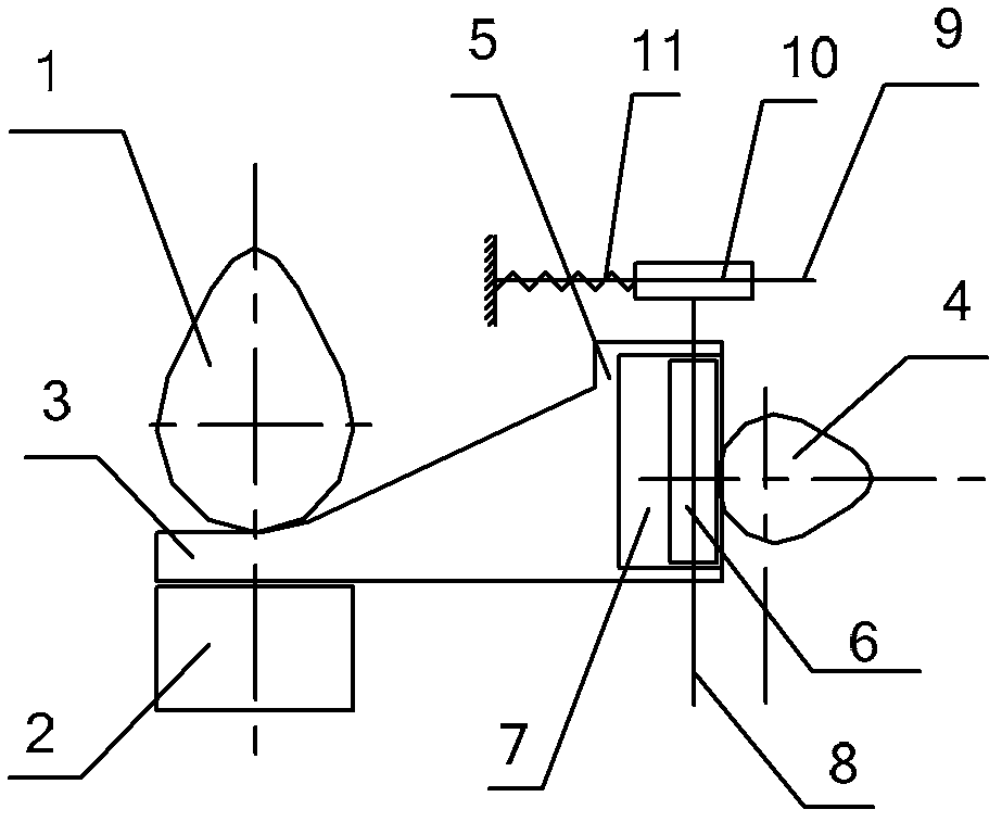
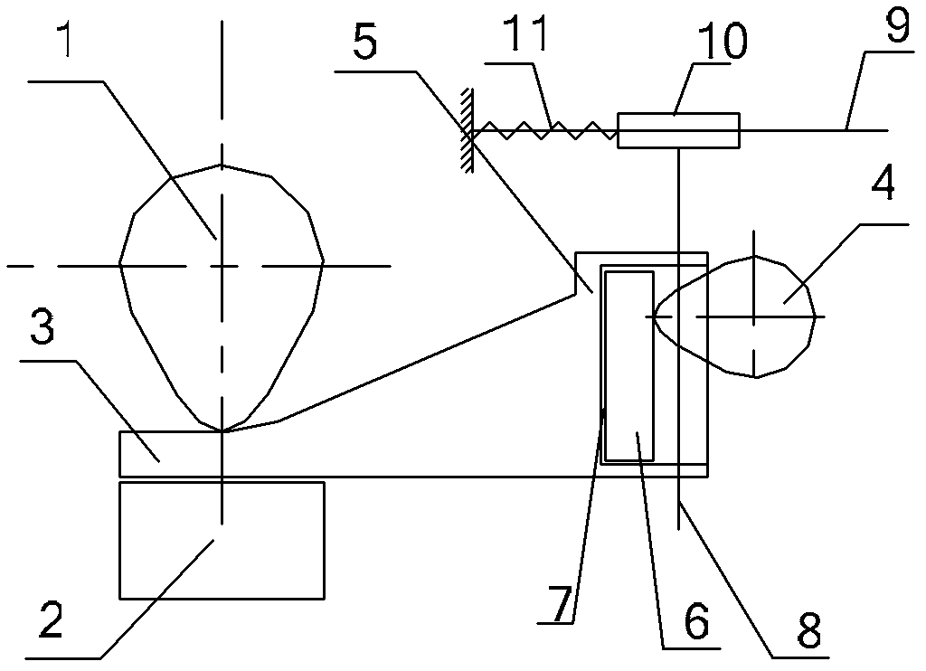
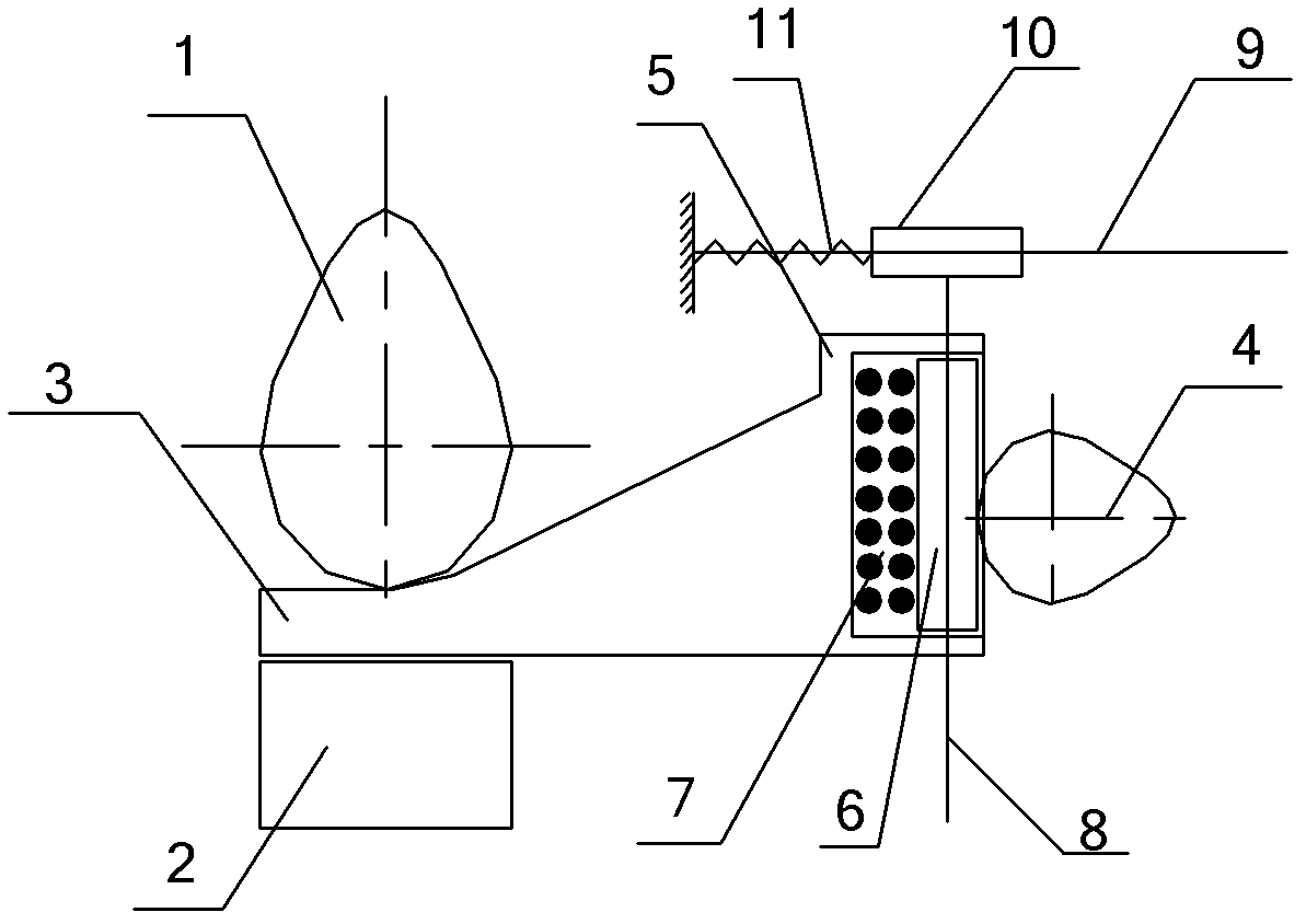
[0036] Figure 1-Figure 4 Both are partial structural schematic diagrams of the engine valve train provided by Embodiment 2 of the present invention, wherein figure 1 Shown is the valve closed state of the engine valve train under one valve lift, figure 2 Shown is the valve fully open state of the engine valve train under one valve lift, image 3 Shown is the valve closed state of the engine valve train under another valve lift, Figure 4 Shown is the fully open state of the valve mechanism of the engine under another valve lift. Embodiment 2 of the present invention provides an engine valve mechanism, which is based on Embodiment 1, and further provides a preferred solution, wherein the part between the sliding plate 3 protruding from the cam and the transmission mechanism 2 is formed with a sliding plate body 5 The side of the slide body 5 away from the camshaft 1 is provided with an accommodation groove; the slide control device also includes a movable block 6, which is...
PUM
 Abstract
Description
Claims
Application Information
 - R&D Engineer
- R&D Manager
- IP Professional
- Industry Leading Data Capabilities
- Powerful AI technology
- Patent DNA Extraction
Browse by: Latest US Patents, China's latest patents, Technical Efficacy Thesaurus, Application Domain, Technology Topic, Popular Technical Reports.
© 2024 PatSnap. All rights reserved.Legal|Privacy policy|Modern Slavery Act Transparency Statement|Sitemap|About US| Contact US: help@patsnap.com