
Filter arrangement, in particular air filter arrangement

A filter device and filter element technology, applied in membrane filters, dispersed particle filtration, dispersed particle separation, etc., can solve problems such as excitation vibration

Active Publication Date: 2013-03-20
MAHLE INT GMBH
View PDF5 Cites 0 Cited by
  • Summary
  • Abstract
  • Description
  • Claims
  • Application Information

AI Technical Summary

Problems solved by technology

In the case of filtering devices of the type mentioned at the beginning, the fundamental problem is that the relatively large front wall of the housing excites vibrations

Method used


Image

  • Filter arrangement, in particular air filter arrangement
  • Filter arrangement, in particular air filter arrangement
  • Filter arrangement, in particular air filter arrangement

Examples


Embodiment Construction

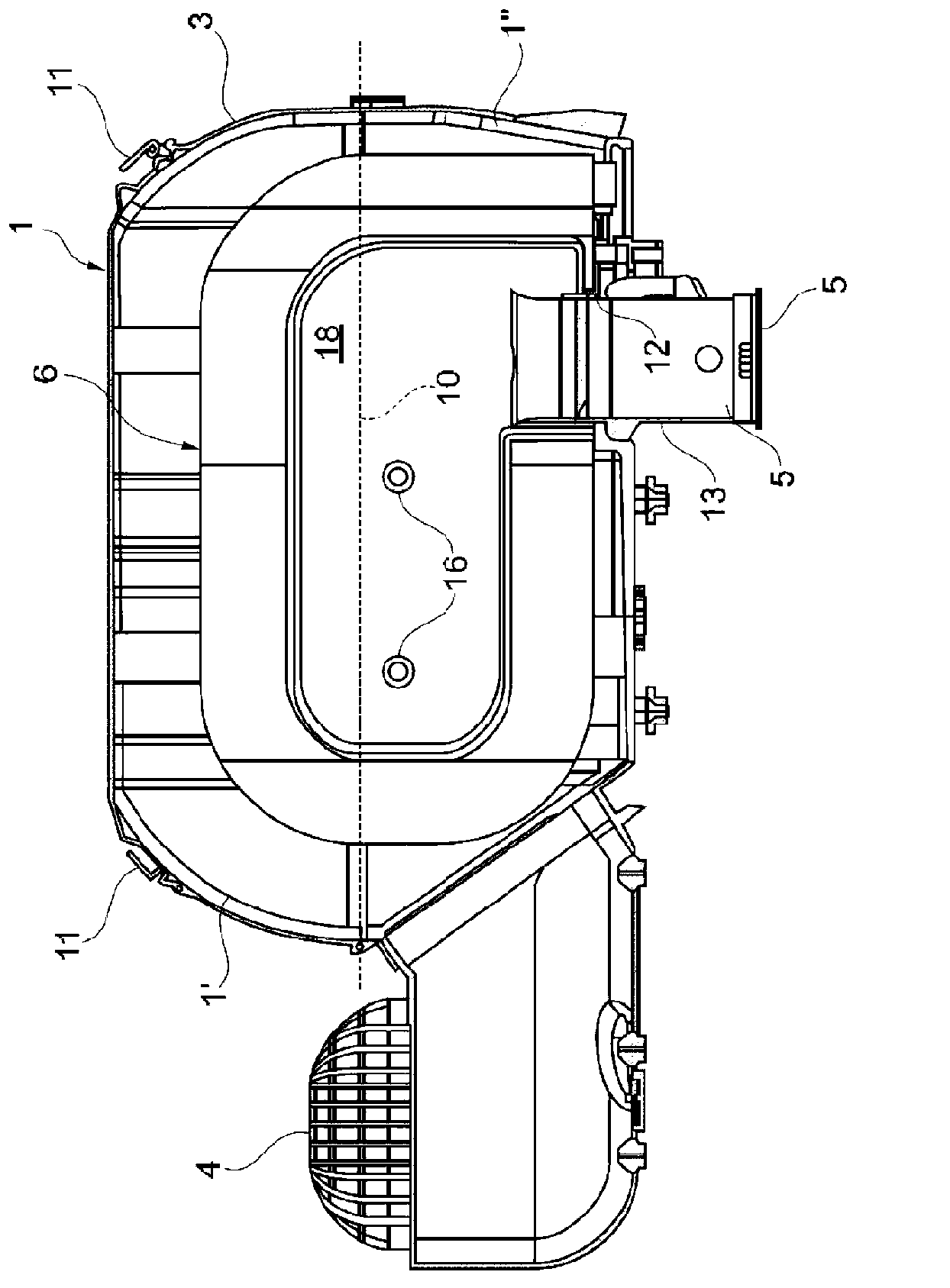
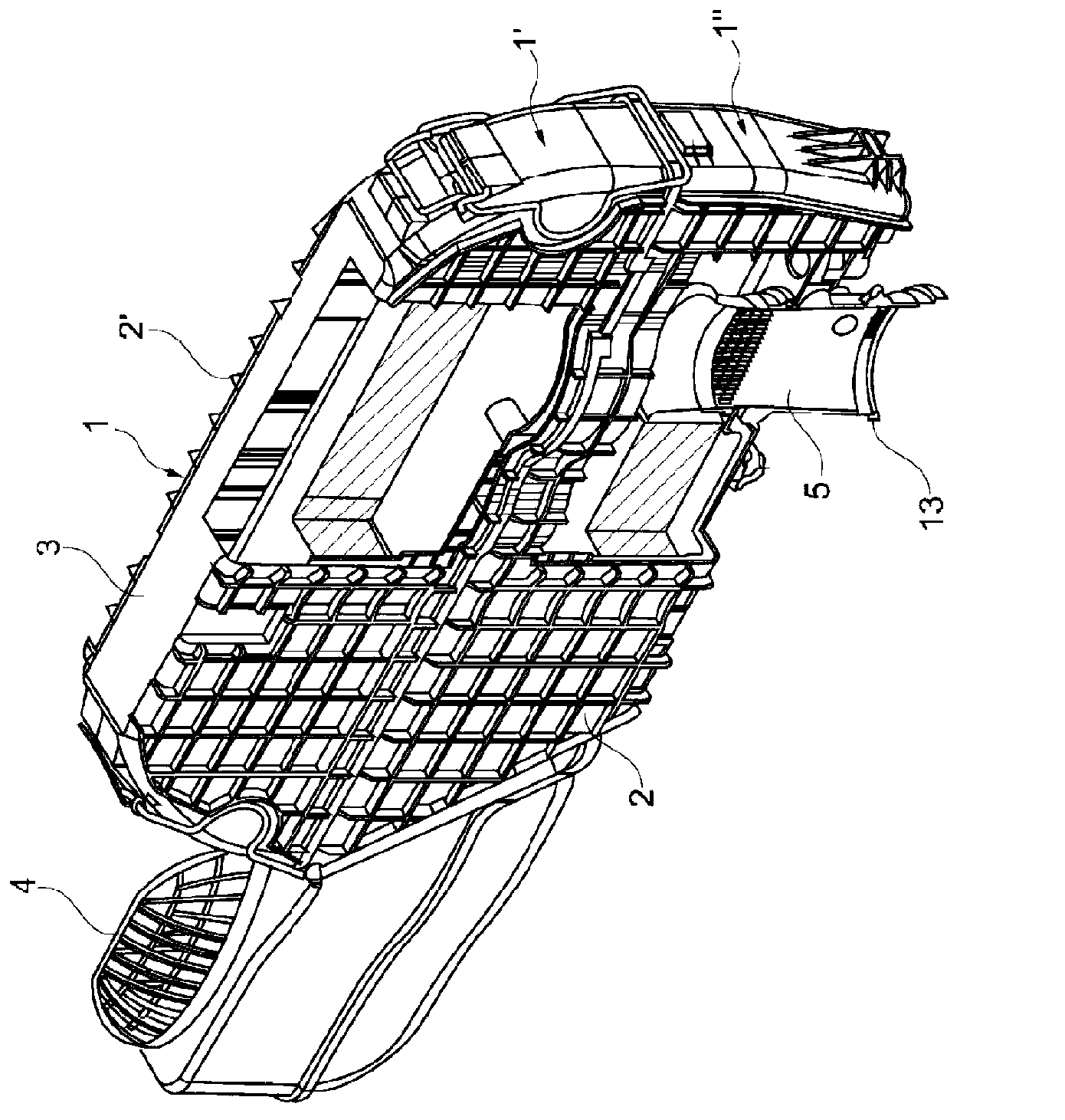
[0025] refer to figure 1 and figure 2 , the air filter device according to the present invention comprises a housing 1 having relatively large side surfaces 2 and 2' connected to each other by a relatively narrow peripheral wall 3. On the peripheral wall 3 , a raw space inlet 4 and a clean space outlet 5 are arranged, wherein the inlet 4 and the outlet 5 are separated by a filter element 6 arranged in the housing 1 .

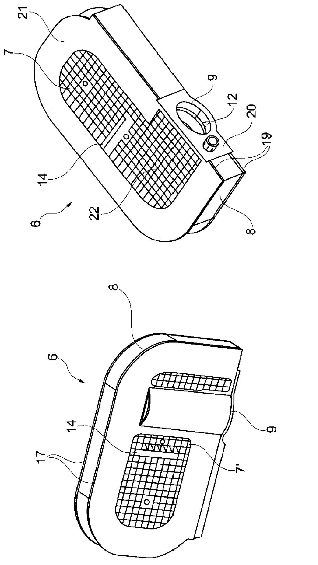
[0026] refer to image 3 , the filter element 6 comprises frontal chassis 7 and 7', which are connected to each other at their respective edge regions by an approximately circumferential filter wall 8, which is folded into an approximate star shape in plan view of the chassis 7, 7', wherein The pleats extend perpendicular to the chassis 7, 7'. This filter wall 8 passes through the long sides 19 of the chassis 7 and 7' through a through hole 9 provided in the side disc 20 and firmly connected to the filter wall 8 and the chassis 7, 7'. In the assem...


PUM


Abstract

Inside a box-like housing there is arranged a filter insert which has two bottom discs (7, 7') directly adjacent to the side walls of the housing. The housing can be divided with respect to a parting plane which is substantially orthogonal to the side walls, wherein profiled strips (100), which are parallel to the parting plane and arranged on the bottom discs (7, 7') of the filter insert, bear in a form- and / or force-fitting manner against the inner side of the side walls of the housing and / or can be fixed on or between those regions of the side wall parts of the housing that are on the parting plane side.

Description

technical field [0001] The present invention relates to filter devices, in particular air filter devices, having a housing comprising two large side walls extending substantially on either side of a central plane of the housing and a peripheral wall substantially perpendicular to the housing The central plane and connects the side walls with the inlet of the untreated space and the outlet of the clean space, the filter device has a filter element, which is effective between the inlet of the untreated space and the outlet of the clean space, said filter element comprises two chassis and filter walls, so The base plate is adjacent to the side wall in the assembled state of the filter element, the filter wall connects the edge area of ​​the base plate substantially perpendicular to the center plane of the housing, and is penetrated by a through hole, which can be firmly connected to the Said untreated space entrance or clean space exit. Background technique [0002] Such air f...

Claims


Application Information

Patent Timeline
Patent Type & Authority Applications(China)
IPC IPC(8): B01D46/52B01D46/00B01D46/10B01D46/42
CPCB01D46/103B01D46/4236B01D2275/206B01D2265/024B01D46/0005B01D46/0006B01D46/521
Inventor 蒂诺·罗特尔马蒂亚斯·特劳布
Owner MAHLE INT GMBH
Learn More