Water-saving device for water closet

A technology for flush toilets and water savers, which is applied to water supply devices, flushing equipment with water tanks, buildings, etc., can solve the problems of inconvenient operation, inability to flush a large amount of water, difficulties, etc., and achieve accurate control, weak power consumption, and simple installation. Effect

Active Publication Date: 2014-06-11
NINGBO YILIN AGUATECH CO LTD
View PDF7 Cites 0 Cited by
  • Summary
  • Abstract
  • Description
  • Claims
  • Application Information

AI Technical Summary

Problems solved by technology

There are several existing technologies: 1. Put a water storage bottle in the water tank to reduce the amount of water when flushing, which can also save water, but it has the disadvantage of not being able to flush with large amounts of water, resulting in unclean flushing Phenomenon
2. Renovate the structure of the flush valve and replace the original flush device with a water valve that distinguishes between large and small water. Because of the non-standard nature of the flush toilet, it is very difficult to transform. It requires a strong hands-on ability and a variety of water valves. It brings great difficulties to the actual transformation, which is not conducive to the promotion of water-saving devices
This transformation method is simple and easy to implement, but there is a disadvantage: the operation is not humane, and the time to press the water release switch is too long. Because there are heavy objects on the leather valve, it will bring a lot of inconvenience to the elderly and children.
Therefore, the existing water-saving methods for flush toilets cannot perfectly solve the water-saving transformation of traditional flush toilets.

Method used


Image

  • Water-saving device for water closet
  • Water-saving device for water closet
  • Water-saving device for water closet

Examples


Embodiment Construction

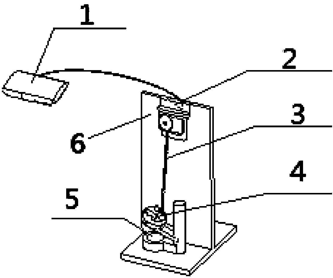
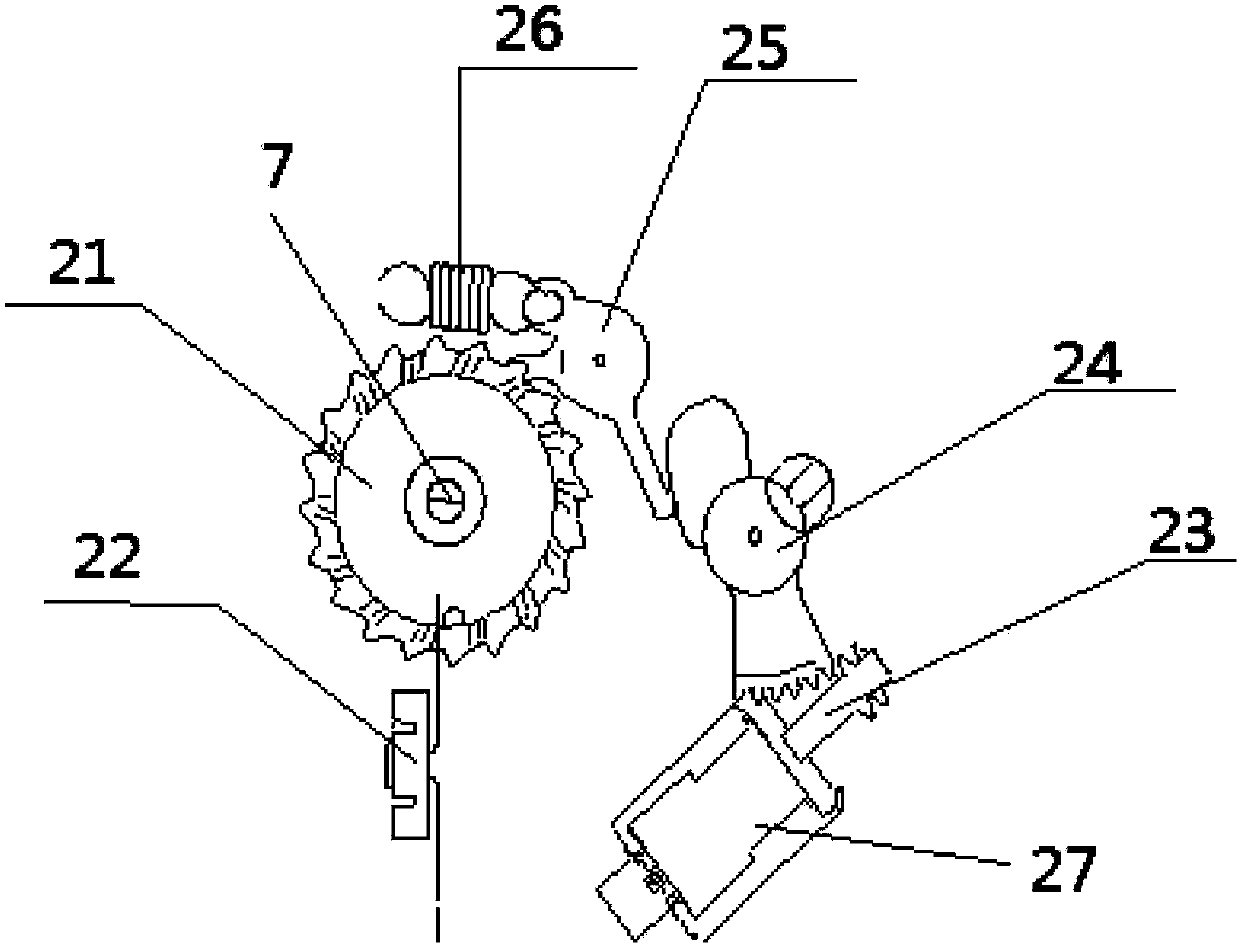
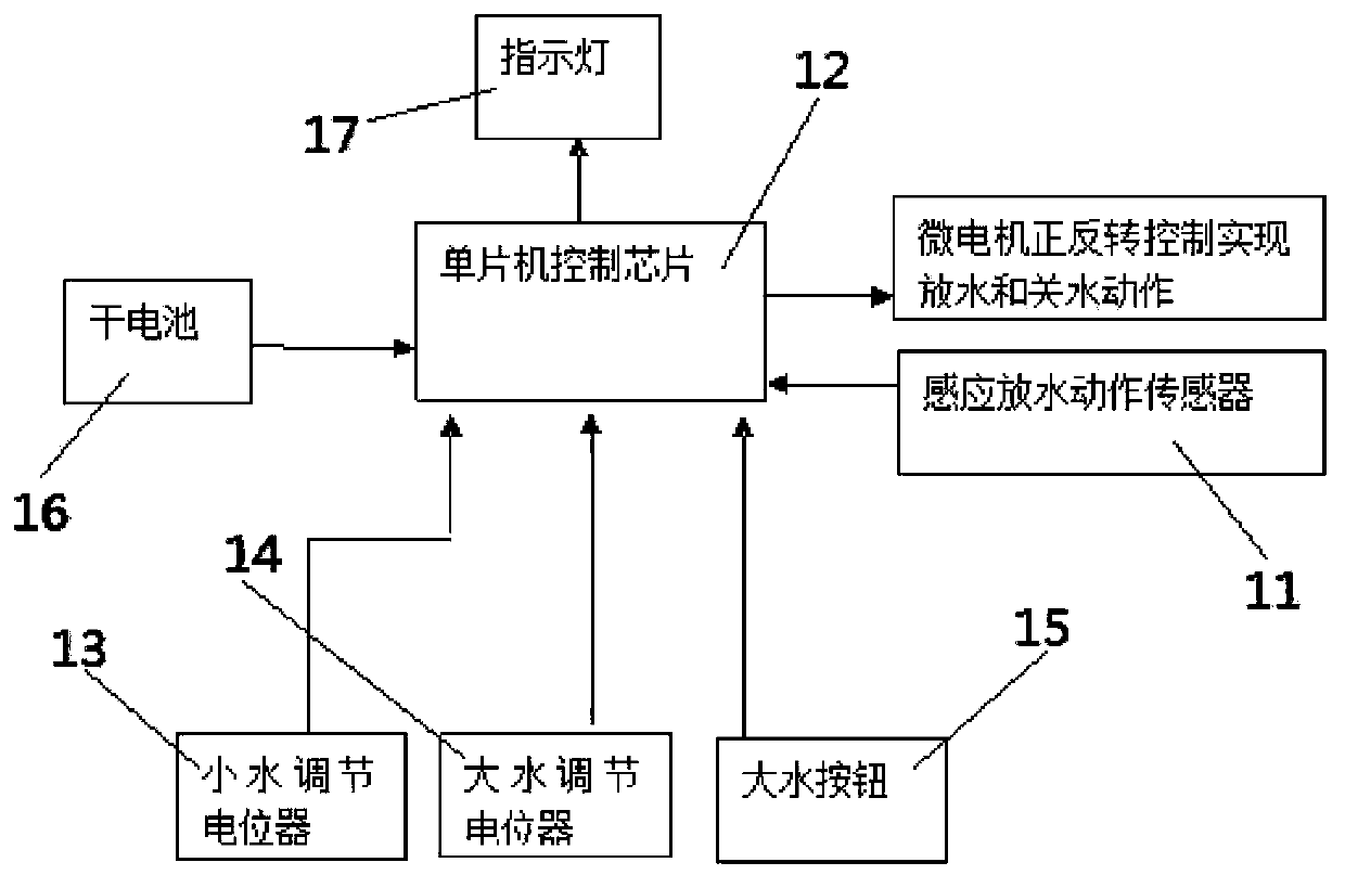
[0012] The present invention will be described in detail below in conjunction with accompanying drawing: figure 1 , 2 , 3, the present invention includes a controller 1, a driving device 2, a zipper 3, a gravity device 4, a flush valve 5, the driving device 2 is connected to the water-discharging rubber part 6 of the toilet, and the controller 1 is located outside the toilet The gravity device 4 is connected to the pulley 21 in the drive device 2 through the slide chain 3, and the pulley 21 is connected to the toilet flush switch 7, and the gravity device 4 is covered on the flush valve 5 in the toilet; the drive device The sensor 22 in the 2 is inductively connected with the inductive water discharge action sensor 11 in the controller 1 through its inductive signal. Described driving device is made of pulley 21, inductor 22, worm rod 23, turbine 24, ratchet 25, turbine spring 26, motor 27, and the power source of described motor 27 comes from dry battery 16 in controller 1, ...


PUM


Abstract

The invention relates to a water-saving device for a water closet, which comprises a controller, a driving device, a zipper, a gravity device and a flushing valve, wherein the driving device is connected on a water discharge rubber part of the water closet; the controller is arranged outside the water closet; the gravity device is connected with a pulley arranged in the driving device by the zipper; the pulley is connected with a flushing switch of the water closet; the gravity device is covered on the flushing valve in the water closet; and a sensor arranged in the driving device is connected with a sensor which is arranged in the controller and used for sensing the water discharge action in a sensing way by a sensing signal. The water-saving device for the water closet has the beneficial effects that the traditional water closet is not needed to be reformed, so that the installation is very simple; the water-saving device is not needed to be adjusted after the flushing water quantity is set, and the flushing quantity can be accurately controlled; when less water is used for flushing, the action is the same as the traditional operation, so that the operation habit is not needed to be changed; and the controller consumes tiny electricity, so that the service life of a dry battery is more than five years.

Description

technical field [0001] The invention relates to the field of flush toilets, in particular to a flush toilet water saver used in traditional flush toilets. Background technique [0002] In traditional flush toilets, the flush switch has no corresponding distinction between large and small water, and a large amount of water is used when flushing to urinate, resulting in a great waste of water resources. In view of the above disadvantages, how to quickly and conveniently transform the toilet into a water-saving toilet without replacing the toilet is a big problem. There are several existing technologies: 1. Put a water storage bottle in the water tank to reduce the amount of water when flushing, which can also save water, but it has the disadvantage of not being able to flush with large amounts of water, resulting in unclean flushing Phenomenon. 2. Renovate the structure of the flush valve and replace the original flush device with a water valve that distinguishes between lar...

Claims


Application Information

Patent Timeline
Patent Type & Authority Patents(China)
IPC IPC(8): E03D5/10
Inventor 林江周和成
Owner NINGBO YILIN AGUATECH CO LTD
Why Eureka
Try Eureka