
Metallurgical rolling mill

A rolling mill and pin shaft technology, applied in the field of metallurgical rolling mills, can solve the problems of sliding bearing 3 unilateral wear, inability to bear axial force, time-consuming and labor-intensive problems, and achieve the effect of eliminating uneven force and avoiding unilateral friction

Active Publication Date: 2015-04-01
SOUTHWEST ALUMINUM GRP
View PDF9 Cites 0 Cited by
  • Summary
  • Abstract
  • Description
  • Claims
  • Application Information

AI Technical Summary

Problems solved by technology

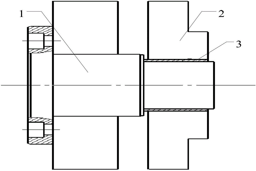
During the rolling process, the sleeve needs to be transported from the side of the uncoiler to the side of the coiler. At present, the rotating pair in the sleeve removal device of the metallurgical rolling mill adopts the form of a sliding bearing. Please refer to figure 1 , that is, the rotating arm 2 is connected to the pin shaft 1 through the sliding bearing 3. The characteristic of the sliding bearing 3 cannot bear the axial force. In the case of uneven radial force, it is easy to cause unilateral wear of the sliding bearing 3, and then damage the pin shaft. 1 and swivel arm 2
Replacing pin shaft 1 and sliding bearing 3 is time-consuming and laborious, affecting production

Method used


Image

  • Metallurgical rolling mill
  • Metallurgical rolling mill

Examples


Embodiment Construction

[0014] The invention provides a metallurgical rolling mill, so that it can improve the stress situation of the sliding bearing in the sleeve removal device, prolong the service life of the sliding bearing, and further reduce the maintenance cost of the metallurgical rolling mill.

[0015] The following will clearly and completely describe the technical solutions in the embodiments of the present invention with reference to the accompanying drawings in the embodiments of the present invention. Obviously, the described embodiments are only some, not all, embodiments of the present invention. Based on the embodiments of the present invention, all other embodiments obtained by persons of ordinary skill in the art without making creative efforts belong to the protection scope of the present invention.

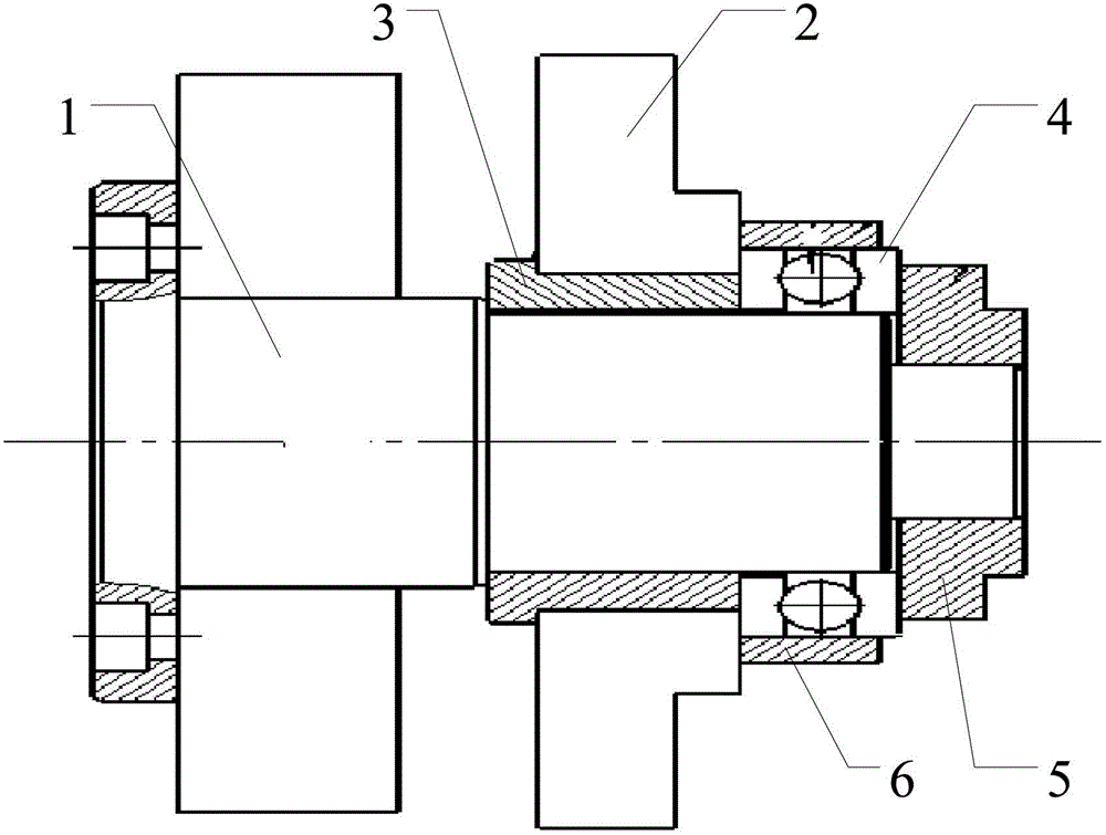
[0016] see figure 2 , figure 2 It is a schematic structural diagram of a sleeve removal device for a metallurgical rolling mill provided by an embodiment of the present invention...


PUM


Abstract

The invention discloses a metallurgical rolling mill. A thrust bearing is additionally arranged on the outer side of a rotating arm of a sleeve move-out device of the metallurgical rolling mill and is tightly pressed by a pressing device. The thrust bearing applies axial force and supplies radial friction to the rotating arm simultaneously, so that the stress unbalance of the rotating arm can be eliminated. Therefore, a sliding bearing can be prevented from being worn due to unilateral frication generated in a rotating process.

Description

technical field [0001] The invention relates to the field of mechanical processing devices, in particular to a metallurgical rolling mill. Background technique [0002] Metallurgical rolling mill is the equipment that realizes the metal rolling process. It generally refers to the equipment that completes the whole process of rolling material production, including main equipment, auxiliary equipment, lifting and transportation equipment and auxiliary equipment. During the rolling process, the sleeve needs to be transported from the side of the uncoiler to the side of the coiler. At present, the rotating pair in the sleeve removal device of the metallurgical rolling mill adopts the form of a sliding bearing. Please refer to figure 1 , that is, the rotating arm 2 is connected to the pin shaft 1 through the sliding bearing 3. The characteristic of the sliding bearing 3 cannot bear the axial force. In the case of uneven radial force, it is easy to cause unilateral wear of the sli...

Claims


Application Information

Patent Timeline
Patent Type & Authority Patents(China)
IPC IPC(8): B21C47/24
Inventor 慕刚毅孔令平
Owner SOUTHWEST ALUMINUM GRP
Learn More