Oil pump device

A technology for oil pumps and pump housings, which is applied in the field of oil pump devices, and can solve problems such as difficulty in forming an output motor, increased driving force loss of the motor, and increased sliding resistance

Inactive Publication Date: 2013-04-10
JTEKT CORP
View PDF3 Cites 12 Cited by
  • Summary
  • Abstract
  • Description
  • Claims
  • Application Information

AI Technical Summary

Problems solved by technology

Concerning the constraints on the arrangement space, the constraints on the winding space of the coils that constitute the motor are also strict, and the diameter and number of windings are also restricted, making it difficult to construct a motor with a large output.
[0006] Therefore, depending on the amount of oil supplied, it is necessary to supply a large current to the motor for driving, resulting in a problem that the efficiency of the motor decreases.
In addition, as the rotational speed of the internal gear increases, the sliding resistance increases, and the loss of the driving force of the motor tends to increase.

Method used


Image

  • Oil pump device
  • Oil pump device
  • Oil pump device

Examples


Embodiment Construction

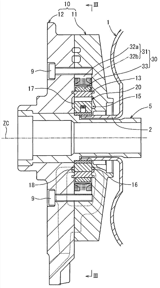
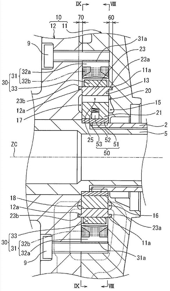
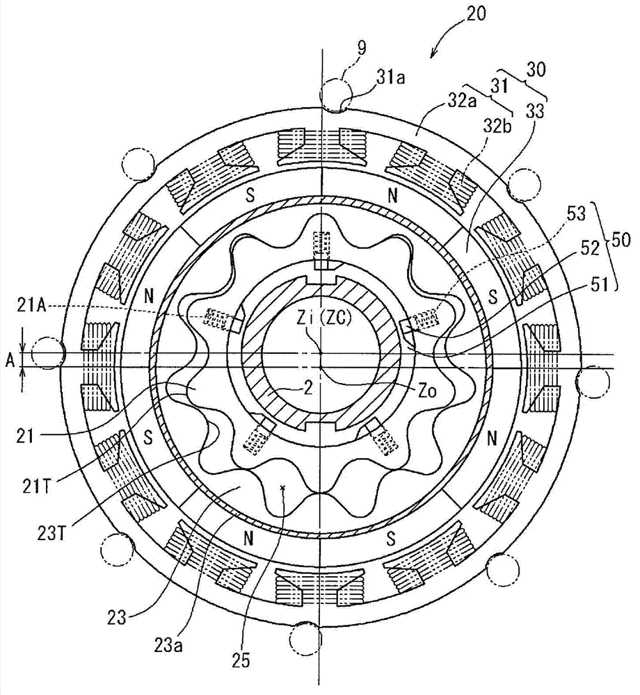
[0019] according to Figure 1 to Figure 7 , the oil pump device according to the embodiment of the present invention will be described.

[0020] like figure 1 As shown, the oil pump device is assembled in the hydraulic torque converter 1 of the automatic transmission. In the oil pump device, the pump housing 10 is fixed to a housing (not shown) of an automatic transmission with bolts. The pump housing 10 is constructed so that the bolts 9 are used to figure 1 The first housing 11 divided in the middle and left and right is combined with the second housing 12 . Between the first housing 11 and the second housing 12, a pump assembly space 13 is formed. More specifically, the pump assembly space 13 consists of an assembly recess formed axially recessed at the center of the inner wall surface of the first housing 11 that faces the second housing 12 , and an assembly recess of the second housing 12 that is aligned with the second housing 12 . A housing 11 is formed on opposite...


PUM


Abstract

The invention provides an oil pump device. The pump housing is assembled with an inner wheel gear, an outer wheel gear and a motor part, and an unidirectional linking mechanism which conducts power transmission from the sleeve side to the inner wheel gear side between the outer periphery of the sleeve and the inner wheel gear, and cuts off power transmission of the opposite direction. The motor part is disposed at the outer periphery of the outer wheel gear in a manner of integrally retaining the rotor and the outer wheel gear and retaining the rotor to the pump housing. The motor part is assembled in that the rotor is rotated with respect to the stator through supplying current, and driving power is transmitted to the outer wheel gear. The inner and outer wheel gears are rotated with respect to each other through the driving power caused by the engine and the driving power caused by the motor part. Accordingly, pump function is generated.

Description

technical field [0001] The present invention relates to oil pump devices. Background technique [0002] Conventionally, when the engine of the vehicle is in operation, in order to supply oil for lubricating, operating, controlling, etc. of various mechanisms, a motor pump is assembled on the automatic transmission (for example, refer to Japanese Patent Laid-Open Publication No. 6-73387, Japanese Patent Laid-Open Publication No. 9-25809). [0003] In addition, there is known a vehicle equipped with an idling stop system that temporarily stops the engine when the vehicle is temporarily stopped. In a vehicle equipped with such an idling stop system, since the motor pump stops when the engine is temporarily stopped (idling stop), oil cannot be supplied to a clutch mechanism or the like in the automatic transmission. [0004] Therefore, in addition to the conventional engine drive, an oil pump device that can drive the motor when the engine is temporarily stopped has also been ...

Claims


Application Information

Patent Timeline
Patent Type & Authority Applications(China)
IPC IPC(8): F04C15/00
CPCF04C2/102F04C15/0061
Inventor 渡边健太郎林则康向出尚正三井哲弥久保厚
Owner JTEKT CORP
Why Eureka
Try Eureka