Electronic device cooling system with auxiliary cooling device

An electronic equipment and auxiliary cooling technology, which is applied in the construction parts of electrical equipment, cooling/ventilation/heating transformation, electrical components, etc., can solve problems such as overheating of inlet temperature, large temperature difference, overheating of inlet temperature of electronic equipment, etc., to achieve The effect of solving the problem of overheating

Active Publication Date: 2013-04-10
深圳市新凯来技术有限公司
View PDF6 Cites 7 Cited by
  • Summary
  • Abstract
  • Description
  • Claims
  • Application Information

AI Technical Summary

Problems solved by technology

[0007] In the existing technology, from the perspective of thermal management in the computer room, in the down-flow fan room, the cabinets are mostly arranged in the form of hot and cold aisles, and the air from the air conditioner enters the raised floor and is sent to the electronic equipment chassis through the perforated floor in the cold aisle. On the inlet side, after passing through the electronic equipment chassis, the hot air is exhausted to the hot aisle and returned to the air conditioner for recooling. However, when the power of a single cabinet exceeds 4kw, due to insufficient cooling air, the hot air in the hot aisle will flow back from the top of the cabinet In the cold aisle, the temperature difference between the upper and lower inlets of the cabinet becomes larger, which makes the inlet temperature of the electronic equipment chassis on the upper part of the cabinet too high, resulting in the problem of overheating of the inlet temperature
[0008] Therefore, in the prior art, the defects of the electronic equipment system include: the air volume distribution is unreasonable, and the devices with high calorific value cannot be effectively cooled; the cascade connection of the front and rear air duct devices will lead to poor cooling effect of the rear devices; Electronic equipment overheating due to high inlet temperature

Method used


Image

  • Electronic device cooling system with auxiliary cooling device
  • Electronic device cooling system with auxiliary cooling device
  • Electronic device cooling system with auxiliary cooling device

Examples


Embodiment Construction

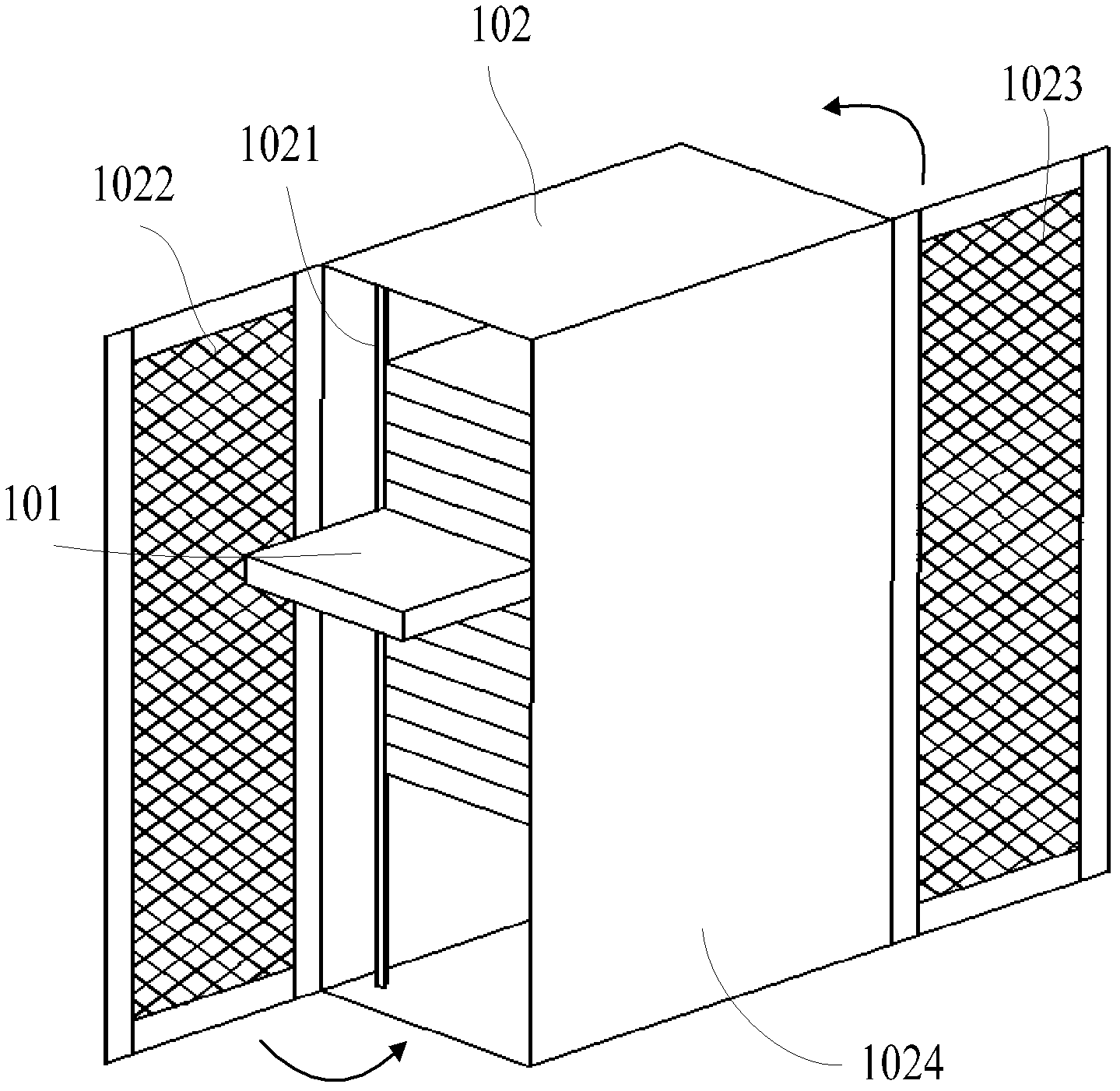
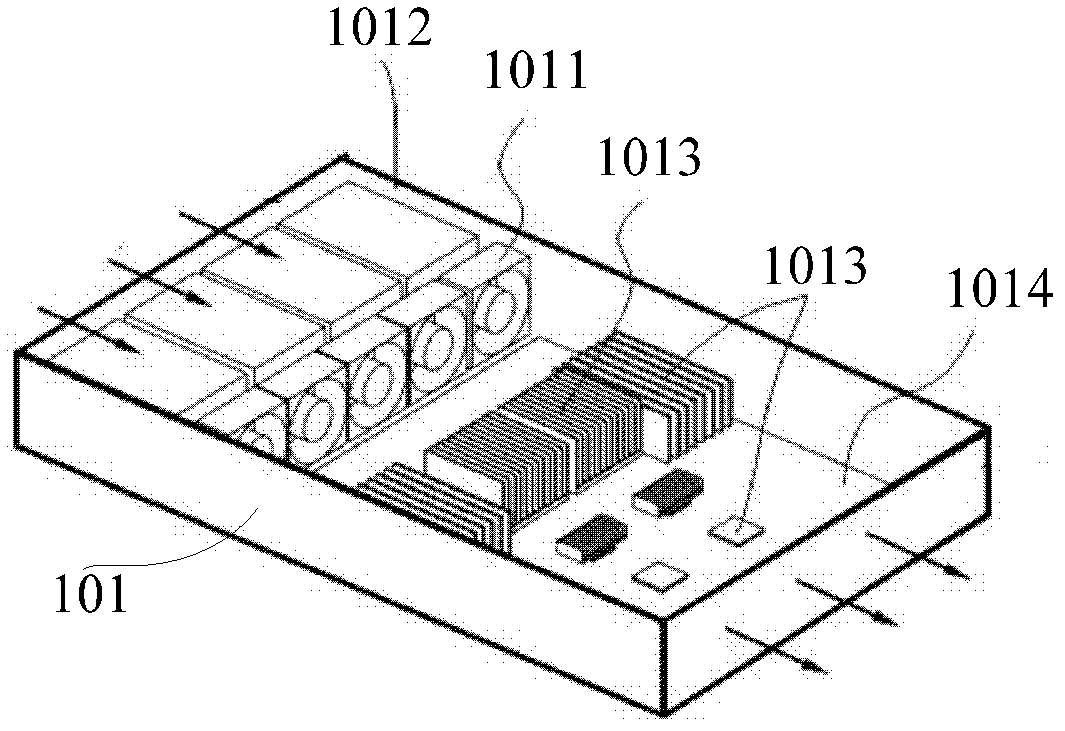
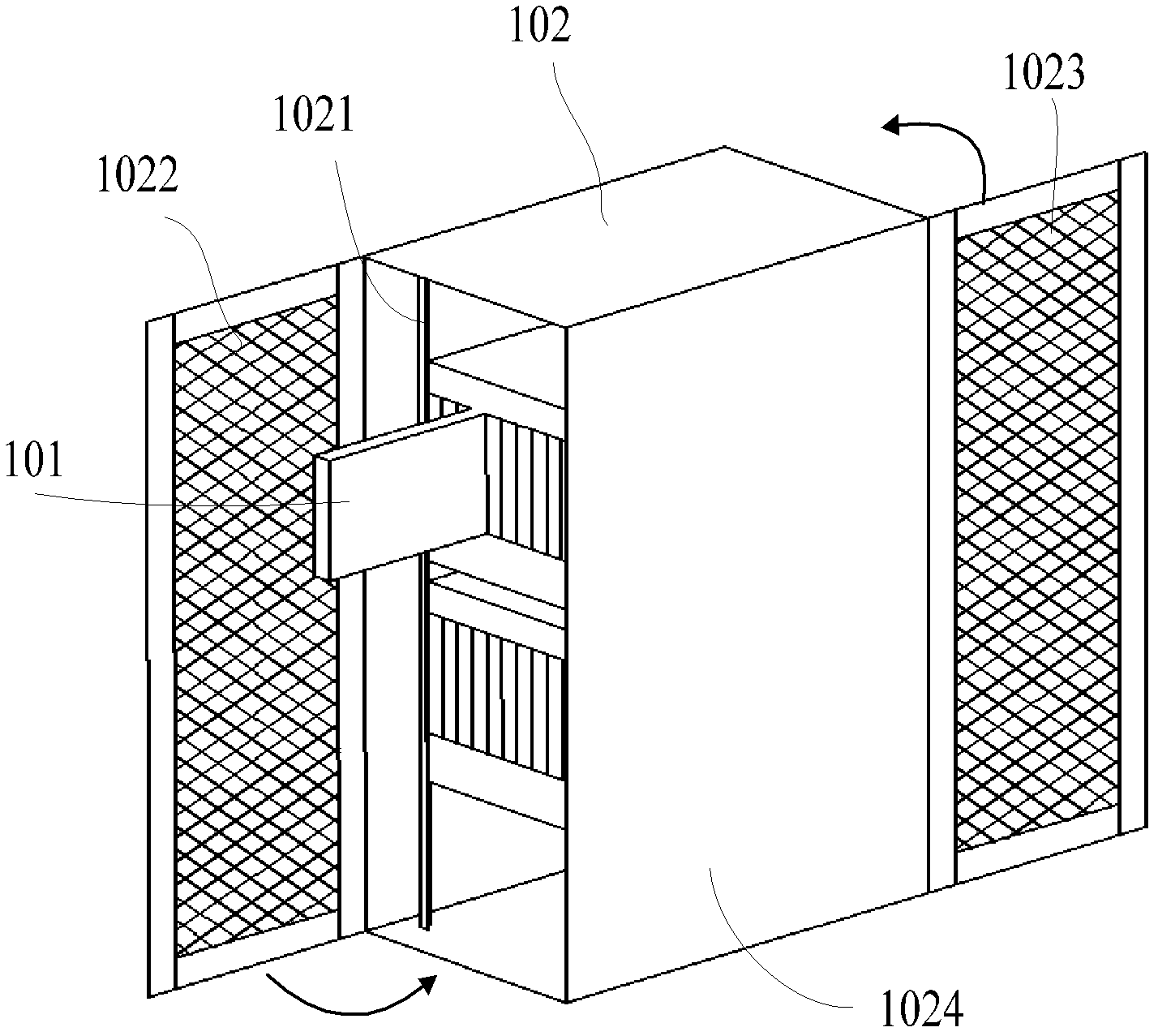
[0023] An embodiment of the present invention provides an electronic equipment cooling system with an auxiliary cooling device, which is used for the electronic equipment cooling system to use its own auxiliary cooling device to cool the devices with high heat generation in the electronic equipment chassis, so that the devices with large heat generation can Effective cooling is obtained without affecting the cooling effect of other devices, and at the same time, the inlet temperature of the devices in the electronic equipment chassis on the upper part of the cabinet can be maintained within an appropriate range to solve the problem of overheating.

[0024] In an embodiment of the present invention, an electronic equipment cooling system with an auxiliary cooling device includes at least one electronic equipment chassis, a cabinet for installing the electronic equipment chassis, and an auxiliary cooling device for dissipating heat from components in the electronic equipment chass...


PUM


Abstract

An embodiment of the invention discloses an electronic device cooling system with an auxiliary cooling device. The electronic device cooling system is used for cooling devices with high heating value in an electronic device machine case. The electronic device cooling system with the auxiliary cooling device comprises a machine cabinet, at least one electronic device machine case which is installed in the machine cabinet, and the auxiliary cooling device. The auxiliary cooling device comprises an air supercharging device, an air supply static pressure box and an air guide device. The air supply static pressure box is arranged on the inner side of the machine cabinet. The air supercharging device is arranged at the top or the bottom of the machine cabinet, and an air outlet on a lateral wall of the air supercharging device is communicated with a corresponding air inlet on a lateral wall of the air supply static pressure box. The air guide device is installed in the electronic device machine case, an air inlet of the air guide device is communicated with an air outlet of the air supply static pressure box, and an air outlet of the air guide device is aligned at the devices in the electronic device machine case.

Description

technical field [0001] The invention relates to the technical field of machine room cabinet cooling, in particular to an electronic equipment cooling system with an auxiliary cooling device. Background technique [0002] The components of electronic equipment will generate heat during operation, causing the temperature of the device to rise. If the temperature of the device exceeds the operating range, it will cause changes in electrical performance and cause the device to fail. Therefore, to ensure the normal operation of the equipment, The equipment must be effectively cooled. [0003] In the prior art, the server is a relatively common type of electronic equipment, which is generally installed on a 19-inch rack in a standard industrial cabinet. When installing a rack-mounted electronic equipment case such as a server, after the electronic equipment case is installed on the rack, there is a certain gap between the electronic equipment case and the side plate of the cabine...

Claims


Application Information

Patent Timeline
Patent Type & Authority Applications(China)
IPC IPC(8): H05K7/20
CPCH05K7/20736H05K7/20727H05K7/20581
Inventor 董愿翟立谦池善久赵钧
Owner 深圳市新凯来技术有限公司
Why Eureka
Try Eureka