Deflecting fence type square heat exchanger with waved tube

A baffle and wave tube technology, applied in the field of heat exchangers, can solve the problem that the shell-side structure cannot meet the design requirements of water-water heat exchange, cannot meet the technical requirements for the production and use of heat exchangers, and the structure of heat exchange tubes is complex. and other problems, to achieve the effect of good self-cleaning ability, inhibition of dirt deposition, and convenient and feasible installation process

Inactive Publication Date: 2013-04-17
HARBIN ENG UNIV
View PDF5 Cites 15 Cited by
  • Summary
  • Abstract
  • Description
  • Claims
  • Application Information

AI Technical Summary

Problems solved by technology

The existing structural design is very simple, and there is no clear plan for important issues such as the structure of the corrugated tube, the specific arrangement in the shell, and the arrangement of the tubes on the tube sheet (patent number: 94225614.U), which cannot meet the needs of replacement. Technical requirements for the actual production and use of heaters
Other conceptual designs also have outstanding problems such as complex structure of heat exchange tubes, difficulty in processing and manufacturing, and difficulty in withstanding high pressure, and the shell side structure cannot meet the design requirements of water-water heat exchange, and the application is limited to the cooling system of automobile exhaust gas (patent No.: 200610165381.4)

Method used


Image

  • Deflecting fence type square heat exchanger with waved tube
  • Deflecting fence type square heat exchanger with waved tube
  • Deflecting fence type square heat exchanger with waved tube

Examples


Embodiment Construction

[0029] The present invention is described in more detail below in conjunction with accompanying drawing example:

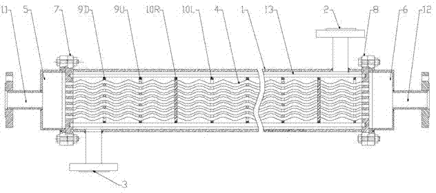
[0030] combine Figure 1~5 , the wave tube baffle grid type square heat exchanger of the present invention comprises a square shell 1, a shell-side inlet pipe 2, a shell-side outlet pipe 3, a heat exchange tube bundle 4, an upper head 5, a lower head 6, a tube sheet 7, 8. Transverse baffles 9D, 9U, longitudinal baffles 10R, 10L, tube-side inlet 11, tube-side outlet 12 and pull rod 13. The side inlet pipe 2 and the shell side outlet pipe 3 of the upper shell of the shell 1 adopt the form of side inlet and side outlet, and are installed at the two ends of the shell side close to the lower head 6 and the upper head 5, and flow in and out along the direction perpendicular to the shell. Out of the shell side space, the angle between the shell side inlet pipe 2 and the shell side outlet pipe 3 can be any angle according to the installation requirements, the pipe side i...


PUM


Abstract

The invention provides a deflecting fence type square heat exchanger with a waved tube. The heat exchanger comprises a case, a heat exchange tube, an upper tube plate and a lower tube plate, wherein the case, the upper tube plate and the lower tube plate form airtight space, an airtight upper head is arranged on the left side of the upper tube plate, an airtight lower head is arranged on the right side of the lower tube plate, a tube-side inlet is arranged on the upper head, a tube-side outlet is arranged on the lower head, the heat exchange tube is installed in the airtight space, two ends of the heat exchange tube are installed in the upper tube plate and the lower tube plate respectively and communicated with the upper head and the lower head respectively, a tube-side outlet tube is arranged on the right of the upper tube plate on the case, a tube-side inlet tube is arranged on the left of the lower tube plate, and a deflecting fence for supporting the heat exchange tube is mounted in the case and comprises a deflecting ring and a support rod installed in the deflecting ring. According to the heat exchanger, vortex flow and the Venturi effect can occur when shell pass fluid flows through the square deflecting fence, so that the shell pass fluid can obtain good turbulent current conditions, dead flow zones and leakage current losses when the fluid flows across tube bundles are reduced, and heat exchange on the shell side is strengthened.

Description

technical field [0001] The invention relates to a heat exchanger in the technical field of enhanced heat exchange. Background technique [0002] Heat exchange equipment is widely used in engineering technology fields such as energy, power, nuclear energy, petroleum, refrigeration, chemical industry and processing. [0003] With the development of science and technology and the shortage of energy, it is of great significance to design and manufacture a heat exchange equipment with high efficiency, low energy consumption and low cost for saving energy. The shell-and-tube heat exchanger is the most widely used type of heat exchanger. For a long time, the heat transfer enhancement of the shell-and-tube heat exchanger has been mainly concentrated on two aspects: tube side strengthening and shell side strengthening. [0004] In terms of tube side enhancement, one of the main directions is to achieve enhanced heat transfer by changing the shape of the heat exchange tube. The corr...

Claims


Application Information

Patent Timeline
Patent Type & Authority Applications(China)
IPC IPC(8): F28D7/00F28F9/013F28F9/24F28F1/08
Inventor 范广铭孙中宁张东洋徐慧强阎昌琪孙立成曹夏昕王建军丁铭谷海峰
Owner HARBIN ENG UNIV
Why Eureka
Try Eureka