Memristor-based non-volatile D trigger

A memristor, non-volatile technology, applied in the field of non-volatile D flip-flops, can solve the problems of increasing hardware cost, complex timing control circuit, state retention and processing time increase, etc., achieving simple structure, small implementation area, convenient The effect of preparation

Active Publication Date: 2013-04-17
HUAZHONG UNIV OF SCI & TECH
View PDF5 Cites 10 Cited by
  • Summary
  • Abstract
  • Description
  • Claims
  • Application Information

AI Technical Summary

Benefits of technology

This patented technology allows for more efficient data processing without requiring an extra memory device or complicated hardware components. It achieves this through utilizing multiple memristive elements arranged into antiparallel connections instead of serially connecting them together. By doing things like adding resistances between certain parts of each element, the resulting circuit becomes less sensitive to changes made during normal operations due to its ability to maintain stable voltage levels even when there are fluctuations from varying sources such as AC voltages. Additionally, these techniques allow for flexible control over how much energy they consume while still providing reliable results at reasonable cost.

Problems solved by technology

The technical problem addressed by this patented technology relates to improving the efficiency with which electronic components such as flippers work together during different states while also being able to keep their stored data intact even after they turn on again at resting (power down). This would make them more reliable and efficient than existing designs without requiring extra equipment.

Method used


Image

  • Memristor-based non-volatile D trigger
  • Memristor-based non-volatile D trigger
  • Memristor-based non-volatile D trigger

Examples


Embodiment Construction

[0025] In order to make the object, technical solution and advantages of the present invention clearer, the present invention will be further described in detail below in conjunction with the accompanying drawings and embodiments. It should be understood that the specific embodiments described here are only used to explain the present invention, not to limit the present invention.

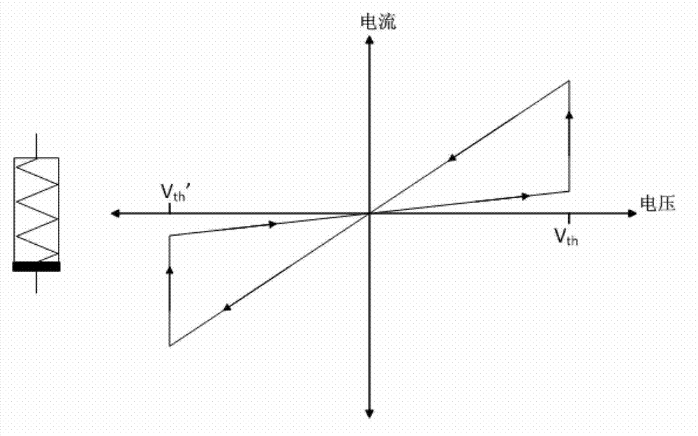
[0026] Figure 1a is a graph of the current-voltage characteristics exhibited when a single memristor is used. from Figure 1a It can be seen that when the forward voltage value is greater than a certain threshold V th , the memristor will become a low resistance state; and when the negative voltage is greater than a certain threshold V th′ , the memristor turns into a high-impedance state.

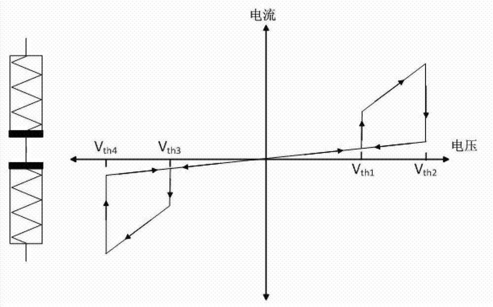
[0027] Figure 1b shows the current-voltage curve exhibited when two memristors in anti-phase series are employed. Such as Figure 1b As shown in , for the first memristor RM1 and the second memristor RM2...


PUM


Abstract

The invention discloses a memristor-based non-volatile D trigger. The D trigger is of a master-slave latch structure, wherein a circuit of each latch comprises a memristor module which is formed by connecting two memristors in series in an inverted manner; and non-volatile latch and trigger functions are executed through the memristor module. The invention also discloses a specific circuit structure of the latch. According to the D trigger, the non-volatile latch and trigger functions can be realized by fully utilizing resistance state difference and a non-volatile characteristic of the memristors; the constructed D trigger has the functions of the conventional trigger, has the characteristic of non-volatility and is suitable for the application field with instable power; and the operation can be continuously performed.

Description


Claims


Application Information

Patent Timeline
Owner HUAZHONG UNIV OF SCI & TECH
Why Eureka
Try Eureka