Hydraulic slewing connector with large slewing angle

A technology of swivel joints and swivel angles, applied in the direction of load hanging components, earth movers/excavators, construction, etc., can solve the problems of the influence of the rotary body and the rotary shaft, short life of the pipeline, poor sealing performance, etc., to achieve The effects of reducing labor intensity, long pipeline life, and improving applicability

Inactive Publication Date: 2013-04-24
JIANGSU CHANGLING HYDRAULIC CO LTD
View PDF0 Cites 2 Cited by
  • Summary
  • Abstract
  • Description
  • Claims
  • Application Information

AI Technical Summary

Problems solved by technology

[0003] However, the sealing performance between the rotary joint and the outside world in the past is poor, and the dust from the outside is easy to get into the rotary joint, which affects the performance of the rotary joint, and the oil in the rotary joint is also easy to leak out. The rotation also has an impact, requiring frequent oiling, which increases the labor intensity of the workers
[0004] Moreover, after the conventional rotary joint is connected to the hydraulic pipeline and the circuit of the fixed part and the rotating part in the hydraulic system and the circuit, the relative rotation angle of the fixed part and the rotating part is generally 50° to 80°, and the rotation angle is small, so the operation and maintenance are not easy. Convenience, and interference between pipelines is easy to occur, resulting in short pipeline life

Method used


Image

  • Hydraulic slewing connector with large slewing angle
  • Hydraulic slewing connector with large slewing angle
  • Hydraulic slewing connector with large slewing angle

Examples


Embodiment Construction

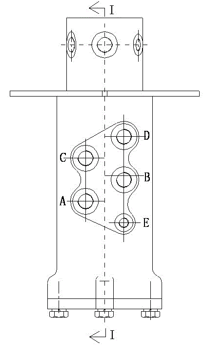
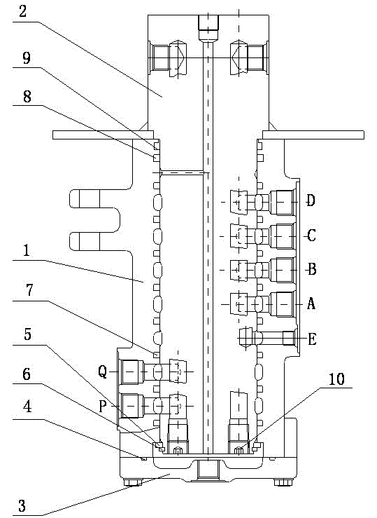
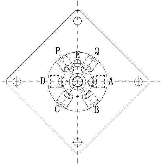
[0017] see Figure 1 to Figure 5 , the present invention relates to a rotary joint with a large rotary angle, comprising a rotary body 1 and a rotary shaft 2, the lower end of the rotary shaft 2 is axially inserted into the rotary body 1 from the upper end of the rotary body 1, and the upper end of the rotary shaft 2 is exposed In the revolving body 1, the lower end of the revolving body 1 is provided with an end cover 3, and the end cover 3 is fixed on the lower end of the revolving body 1 by bolts, and an O-shaped Ring I4, a retaining ring 5 and a shaft elastic retaining ring 6 are provided between the lower end of the rotary body 1 and the lower end of the rotary shaft 2, and a rotary seal is installed in the annular groove between the rotary body 1 and the rotary shaft 2 Ring 7, O-ring II 8 and dust-proof ring 9, the side of the dust-proof ring 9 in contact with the rotary shaft 2 is provided with two upper and lower lips 9.1 to form a double lip, and the upper and lower t...


PUM


Abstract

The invention relates to a hydraulic slewing connector with a large slewing angle. The hydraulic slewing joint comprises a slewing body (1) and a slewing shaft (2). The hydraulic slewing connector is characterized in that the lower end of the slewing shaft (2) is axially inserted inside the slewing body (1) from the upper end of the slewing body (1), a central oil discharge hole, six main oil way holes and a low-pressure oil way hole are formed in the slewing shaft (2) axially, a rotary seal ring (7), an O-shaped ring II (8) and a dust-proof ring (9) are arranged inside an annular groove between the slewing body (1) and the slewing shaft (2), two lip mouths (9.1) up and down are formed on one side, contacting with the slewing shaft (2), of the dust-proof ring (9) to form double lip mouths, and both the two lip mouths (9.1) up and down are tightly attached to the outer wall of the slewing shaft (2). The hydraulic slewing connector with the large slewing angle has the advantages that dust cannot enter easily, oil cannot leak out easily, interference cannot happen among pipelines, and operation and maintenance are very convenient.

Description

technical field [0001] The invention relates to a rotary joint with a large rotary angle, which is mainly used in the hydraulic systems of large-tonnage excavators, cranes, graders, tower cranes and other machinery, and is a hydraulic pipeline connecting the fixed part and the rotating part of the entire hydraulic system and circuit. A connecting piece with a circuit belongs to the technical field of engineering machinery. Background technique [0002] For hydraulic excavators, cranes, loaders, etc., the upper and lower parts need to be rotated, so there is a problem of connecting the oil circuit and the circuit between the rotating part and the fixed part. The rotary joint is composed of a rotary body, a rotary shaft and a cover. When in use, the revolving body is fixed to the revolving lower platform of hydraulic excavators and cranes, and the mounting plate on the revolving shaft is connected with the slewing support on the revolving upper platform. Hydraulic rubber hos...

Claims


Application Information

Patent Timeline
Patent Type & Authority Applications(China)
IPC IPC(8): E02F9/22B66C13/12
Inventor 夏泽民张爱军陈酉冰潘逸明高海波朱江华
Owner JIANGSU CHANGLING HYDRAULIC CO LTD
Why Eureka
Try Eureka