
Planar test device for rock slope destruction and test method thereof

A technology for rock slopes and test devices, which is applied in the direction of measuring devices, machine/structural component testing, instruments, etc., can solve the problems of limited number of tests, low utilization rate of test devices, and influence on the test process, so as to improve the test process , The structure is simple and novel, and the effect of improving the test efficiency

Inactive Publication Date: 2013-04-24
CENT SOUTH UNIV
View PDF6 Cites 12 Cited by
  • Summary
  • Abstract
  • Description
  • Claims
  • Application Information

AI Technical Summary

Problems solved by technology

With this method, the next model can be poured after the slope model in the test device is loaded and destroyed, resulting in low utilization of the test device, affecting the test process, and limiting the number of tests

Method used


Image

  • Planar test device for rock slope destruction and test method thereof
  • Planar test device for rock slope destruction and test method thereof
  • Planar test device for rock slope destruction and test method thereof

Examples


Embodiment 1

[0036] Example 1: Research on the Influence of Main Control Joint Dip Angle on Rock Slope Failure under Slope Top Load

[0037] (1) On a rocky slope of a highway, field geological surveys show that there is a main controlling joint in the slope body. The influence of the main controlling joint dip angle on the rock slope failure under the action of the slope top load is analyzed, and the joint dip angle changes from 0 degrees to 90 degrees degrees, and the inclination increment is 15 degrees, that is, 0 degrees, 15 degrees, 30 degrees, 45 degrees, 60 degrees, 75 degrees and 90 degrees respectively, a total of 7 schemes, and three identical models are poured for each scheme. According to the proportional relationship between the slope model and the prototype, the slope mold is made, and the slope model materials are prepared according to the weight ratio of each material, gypsum: barite: fine sand: water = 1:1:2:1. The slope model is poured, and mica sheets are used to simulate...

Embodiment 2

[0044] Example 2: Research on the influence of main control joint dip angle on rock slope failure under the action of gravity increase

[0045](1) On a rocky slope of a highway, field geological survey shows that there is a main controlling joint in the slope body. The influence of the dip angle of the main controlling joint on the failure of the rock slope under the action of increasing gravity is analyzed, and the dip angle of the joint varies from 0° to 90° , the inclination increment is 15 degrees, that is, 0 degrees, 15 degrees, 30 degrees, 45 degrees, 60 degrees, 75 degrees and 90 degrees are taken respectively, and there are 7 schemes in total, and three identical models are poured for each scheme. According to the proportional relationship between the slope model and the prototype, the slope mold is made, and the slope model materials are prepared according to the weight ratio of each material, gypsum: barite: fine sand: water = 1:1:2:1. The slope model is poured, and ...


PUM


Abstract

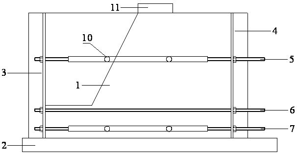
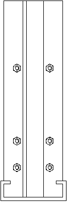
The invention discloses a planar test device for rock slope destruction and a test method thereof. The structure of the test device includes that a slope model is placed in a groove of a base, two organic glass boards are tightly fixed in screw holes through screws, the two organic glass boards are respectively located between a lower end threaded rod and a middle threaded rod, and between an upper end threaded rod and the slope model, and a cushion block is arranged on the top of the slope model. Slop models are machined in batch and then transferred to the test device to be loaded in sequence. The test device is simple in structure, is suitable for similar models with different widths and lengths, and strictly meets boundary constraint conditions. A loading device can utilize existing equipment fully. The test device is capable of effectively speeding up the test progress, achieving imitating the destruction process of a rock slope under the function of the increasing of the slope top load or gravity, improving test efficiency, and shortening test time.

Description

technical field [0001] The invention relates to rock-soil mechanics experiment technology, in particular to a plane test device for rock slope failure and an experiment method thereof. Background technique [0002] my country is a country with frequent landslide disasters, and the losses caused by landslides are huge every year. With the vigorous development of my country's infrastructure, more and more engineering construction will encounter landslide problems. Due to the complexity of landslide mechanism, physical model test has become an important research method to reproduce landslide formation. The physical model test is based on the similarity theory, and according to the similarity criterion, a slope model with a certain proportional relationship with the prototype is made to simulate the failure process of the slope. [0003] Existing physical model tests are generally based on plane models, but the boundary conditions are not strict, and quasi-plane strain conditi...

Claims


Application Information

Patent Timeline
Patent Type & Authority Applications(China)
IPC IPC(8): G01M99/00
Inventor 张科曹平范文臣
Owner CENT SOUTH UNIV
Learn More