Supercharge Your Innovation With Domain-Expert AI Agents!

Wireless communication system, base station, relay station and wireless communication method

A wireless communication system, wireless communication technology, applied in the field of wireless communication systems

Active Publication Date: 2013-04-24
FUJITSU CONNECTED TECH LTD
View PDF4 Cites 0 Cited by
  • Summary
  • Abstract
  • Description
  • Claims
  • Application Information

AI Technical Summary

Problems solved by technology

However, at this moment, the base station does not recognize the sender's device of Msg1

Method used


Image

  • Wireless communication system, base station, relay station and wireless communication method
  • Wireless communication system, base station, relay station and wireless communication method
  • Wireless communication system, base station, relay station and wireless communication method

Examples


no. 1 Embodiment approach

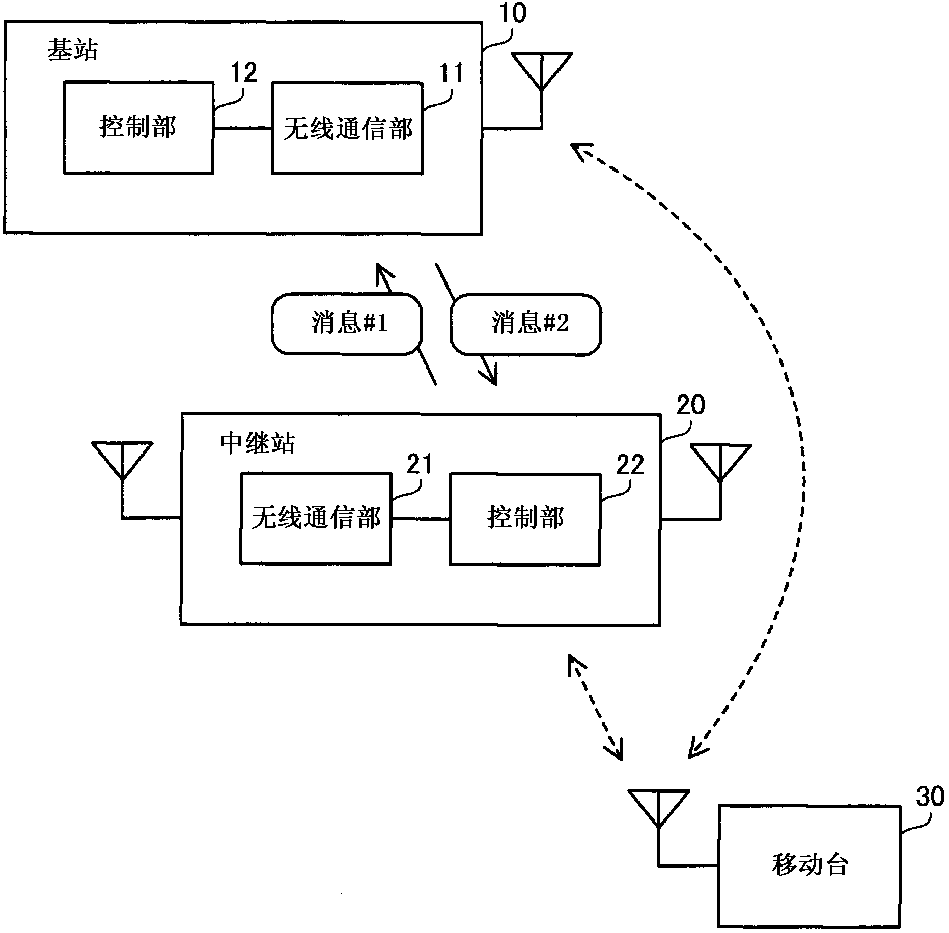
[0059] figure 1 It is a diagram showing the radio communication system of the first embodiment. The wireless communication system according to the first embodiment includes a base station 10 , a relay station 20 and a mobile station 30 . It is assumed that the mobile station 30 is, for example, a mobile phone or a portable information terminal device. The relay station 20 may be a mobile wireless relay station or a fixed wireless relay station. The mobile station 30 performs wireless communication with the base station 10 or the relay station 20 . The relay station 20 can perform random access (RA) to the base station 10 to establish a connection, and can relay data communication between the base station 10 and the mobile station 30 .

[0060] The base station 10 has a wireless communication unit 11 and a control unit 12 . The wireless communication unit 11 receives the first message (message #1) related to random access, and transmits the second message (message #2) relat...

no. 2 Embodiment approach

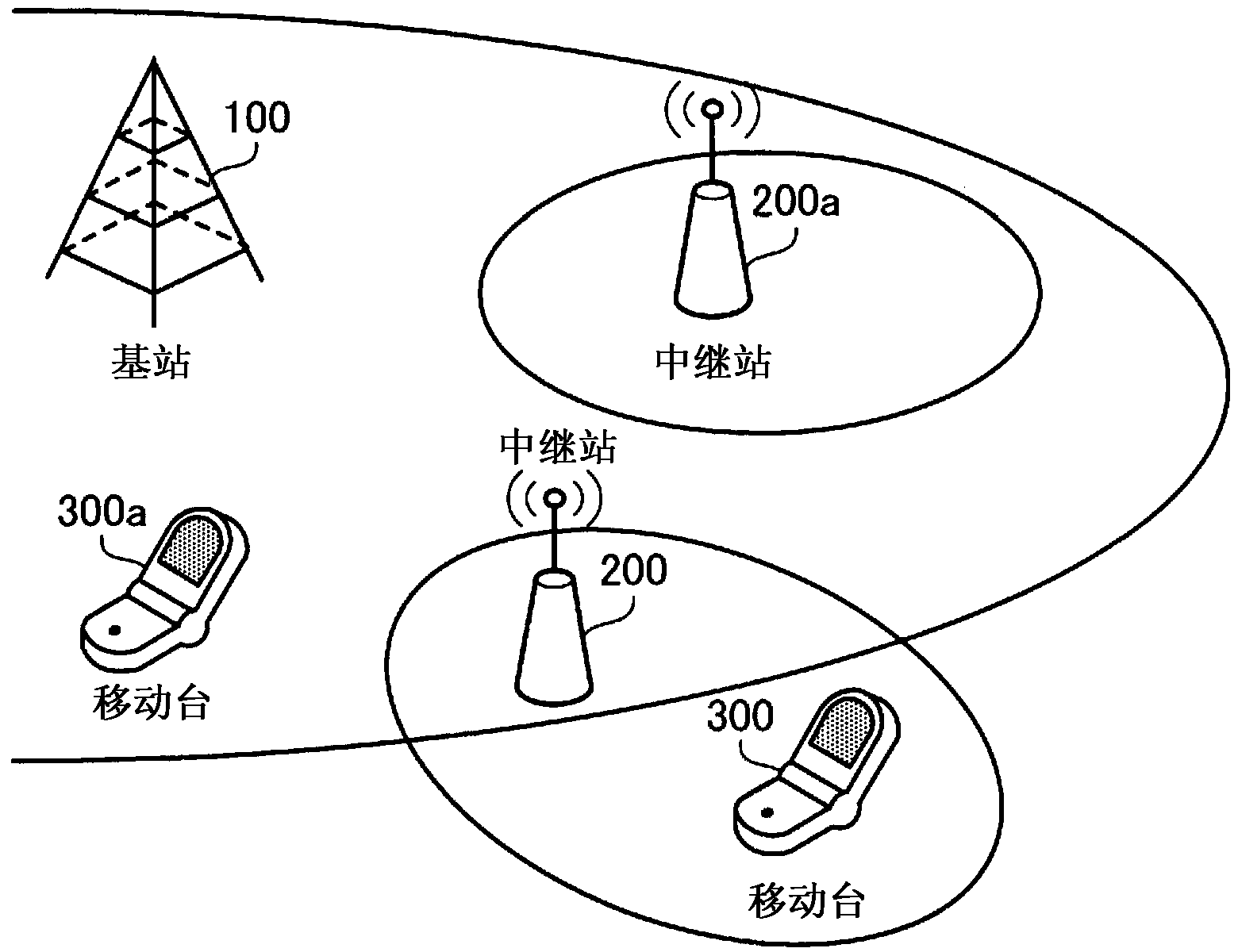
[0068] figure 2 It is a figure showing the wireless communication system of 2nd Embodiment. The wireless communication system of the second embodiment includes a base station 100, relay stations 200, 200a, and mobile stations 300, 300a. In the following description, it is mainly assumed that the mobile station 300 performs data communication with the base station 100 via the relay station 200 and the mobile station 300a directly performs data communication with the base station 100 .

[0069] The base station 100 is a wireless communication device that performs wireless communication with the relay stations 200 and 200a and the mobile station 300a. The base station 100 is wired to an upper station (not shown). The base station 100 receives data from a higher-level station, and transmits it to the relay stations 200 and 200a and the mobile station 300a through a downlink (DL). In addition, data is received from the relay stations 200 and 200a and the mobile station 300a thr...

no. 3 Embodiment approach

[0158] Next, a third embodiment will be described. The description will focus on the differences from the second embodiment, and the description of the same matters will be omitted. In the third embodiment, the method of determining whether the sender of Msg1 is a relay station or a mobile station is different from that in the second embodiment.

[0159] The wireless communication system according to the third embodiment can communicate with figure 2 It is realized with the same device configuration as the second embodiment shown. In addition, the base station, relay station, and mobile station according to the third embodiment can communicate with Figure 6-8 The same block configuration as the second embodiment shown is realized. Use the following with Figure 6-8 The same reference numerals describe the third embodiment.

[0160] Figure 13 It is a flowchart showing base station processing in the third embodiment. numbered pairs along the steps Figure 13 The proce...


PUM


Abstract

The random access by a relay station can be smoothly executed. A relay station (20) wirelessly communicates with a base station (10), and a mobile station (30) wirelessly communicates with the base station (10) or with the relay station (20). The relay station (20) restricts the reception of radio signals from the base station (10) at a timing of transmitting radio signals to the mobile station (30). The relay station (20) transmits, to the base station (10), a message (#1) related to the random access. The base station (10) transmits a message (#2) at a timing that is determined on the basis of whether the transmission source of the message (#1) is the relay station (20) or not. The relay station (20) receives the message (#2) from the base station (10).

Description

technical field [0001] The invention relates to a wireless communication system, a base station, a relay station and a wireless communication method. Background technique [0002] Currently, wireless mobile communication systems such as mobile phone systems and wireless MAN (Metropolitan Area Network: Metropolitan Area Network) are widely used. In addition, in order to further increase the speed and capacity of wireless communication, discussions on next-generation mobile communication technology are being actively and continuously conducted. For example, in 3GPP (3rd Generation Partnership Project: Third Generation Partnership Project), one of the international standardization organizations, a standard called LTE (Long Term Evolution: Long Term Evolution) was proposed, and a standard obtained by extending LTE is called It is a standard of LTE-A (Long Term Evolution-Advanced: see Non-Patent Document 1, for example). [0003] In a wireless communication system including a b...

Claims


Application Information

Patent Timeline
Patent Type & Authority Applications(China)
IPC IPC(8): H04W16/26H04B7/15
CPCH04W74/006H04W72/0446H04W74/002H04B7/15528H04W88/04H04B7/15564H04W74/00H04B7/15H04B7/15507H04W74/0833
Inventor 太田好明河崎义博大渕一央田岛喜晴田中良纪
Owner FUJITSU CONNECTED TECH LTD
Features
  • R&D
  • Intellectual Property
  • Life Sciences
  • Materials
  • Tech Scout
  • Unparalleled Data Quality
  • Higher Quality Content
  • 60% Fewer Hallucinations
Learn More