Photo-communication system based on digital coherent receiver and handling method of output signal

A technology of coherent receiver and optical communication system, applied in the field of optical communication system and output signal processing, can solve the problem that high-speed optical signal cannot be satisfied, digital coherent receiver can not reflect the mitigation of electronic loss, can not meet the real-time detection of high-speed optical signal, etc. problem, to achieve the effect of no need for optical clock recovery, simple structure, and improved accuracy

Active Publication Date: 2015-07-08
河北四方通信设备有限公司
View PDF4 Cites 0 Cited by
  • Summary
  • Abstract
  • Description
  • Claims
  • Application Information

AI Technical Summary

Problems solved by technology

As a result, digital coherent receivers do not have the advantage of mitigating electronic losses
In addition, the pulse repetition rate of the existing local oscillator is 10MHz, which cannot meet the real-time detection of high-speed optical signals. Although the sampling method of parallel light is proposed now (that is, the unit delay of two parallel light samples is used to measure the Measure the differential phase diagram of the differential phase shift keying signal), however, the pulse repetition rate of the local oscillator at this time is still 10MHz, which cannot meet the real-time detection of high-speed optical signals

Method used


Image

  • Photo-communication system based on digital coherent receiver and handling method of output signal
  • Photo-communication system based on digital coherent receiver and handling method of output signal

Examples


Embodiment

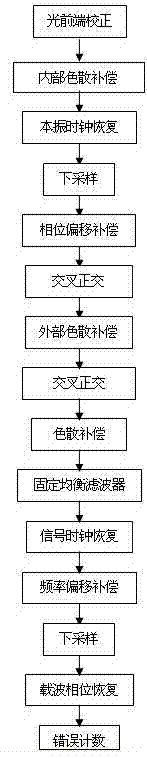
[0050] Example An optical communication system based on digital coherent receiver and its output signal processing method

[0051] 1. An optical communication system based on digital coherent receiver

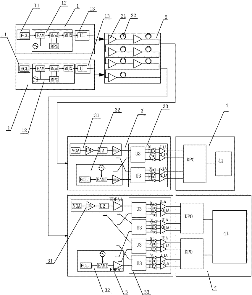
[0052] figure 1 Shown in this embodiment is a schematic structural diagram of an optical communication system based on a digital coherent receiver, including:

[0053] ① The transmitting device 1 composed of a laser emitting module 11, an optical signal modulation delay processing module 12, and a filter module 13, wherein the laser emitting module 11 uses an external cavity laser ECL.

[0054] The optical signal modulation delay processing module includes an electro-absorption modulator EAM, an IQ modulator MOD, and a delay multiplexer MUX. The signal input end of the electro-absorption modulator EAM receives the optical signal from the external cavity laser ECL. The output end is connected to the signal input end of the optical fiber delay multiplexer MUX through the IQ modulator MO...


PUM


Abstract

The invention discloses a photo-communication system based on a digital coherent receiver. The photo-communication system based on the digital coherent receiver comprises a laser transmitting module. Laser which is emitted by the laser transmitting module is connected with a signal input end of an optical signal filtering module through an optical signal modeling and delaying processing module. A signal output end of a filtering module is connected with a signal input end of an optical signal processing module through an optical fiber link. A signal output end of the optical signal processing module is connected with a signal input end of an integrated coherent machine receiving module. A signal output end of a local optical signal production module is connected with a local signal input end of the integrated coherent machine receiving module. The invention further provides a handling method of an output signal of the photo-communication system. The photo-communication system based on the digital coherent receiver has the advantages of being simple in structure, free from optical clock recovery, capable of using a asynchronous pulse local oscillator and capable of automatically conducting polarization compensation and polarization mode compensation, achieves high-speed transmission of signals, reduces electron loss and meanwhile guarantees precision of sampling signals. The photo-communication system based on the digital coherent receiver is suitable for an Ethernet system with a bit rate of 400 giga-bit per second (Gbps) and utilizes a photo-communication system with a 20 Hertz broadband and a 50-Herz sampling rate.

Description

technical field [0001] The invention belongs to the field of optical communication, in particular to an optical communication system based on a digital coherent receiver and a processing method for an output signal. Background technique [0002] At present, in the field of optical communication, digital coherent receivers are usually used as optical acquisition devices, and the digital carrier phase is recovered by means of polarization multiplexing and quadrature phase shift keying, which is used to reduce electronic losses and realize Ethernet high-speed transmission. However, due to the continuous development of science and technology, the transmission rate of Ethernet is also increasing. The current bit rate of Ethernet transmission has reached 400Gdps. The existing digital coherent receivers cannot use the electrical analog-digital signal with a bandwidth of 20GHz and a sampling rate of 50GHz. Converter (ADC). In order to solve the above problems, the researchers prop...

Claims


Application Information

Patent Timeline
Patent Type & Authority Patents(China)
IPC IPC(8): H04B10/61H04B10/524H04B10/291H04B10/2525H04B10/2569H04L7/033
Inventor 张爱民黄新格杨海涛李玉平
Owner 河北四方通信设备有限公司
Why Eureka
Try Eureka