
Method for testing dragging force of rake pipe of trailing suction dredger

A technology of a trailing suction dredger and a detection method, which is applied to force/torque/power measuring instruments, measuring devices, earth movers/shovels, etc., and can solve the impact of drag head life saving, large deviation, and difficulty in improving Problems such as high efficiency of mud suction have achieved the effects of wide application range, convenient detection and strong practicability

Active Publication Date: 2014-07-02
CCCC TIANJIN DREDGING +1
View PDF2 Cites 0 Cited by
  • Summary
  • Abstract
  • Description
  • Claims
  • Application Information

AI Technical Summary

Problems solved by technology

Since the rake head of the dredger is carried out underwater, it is difficult for the staff to judge the actual working state of the rake head, so it is difficult to improve the high efficiency of dredging
On the other hand, if there is too much friction between the rake head and the seabed during the rake suction process, it will also have a serious impact on the service life of the rake head and the energy saving of the ship.
Nowadays, the analysis of the drag head of the dredger, especially the analysis of the friction force of the seabed against the drag head has been in the two-dimensional space analysis model, which has brought some deficiencies in accurately grasping the dynamic process of the drag head, resulting in this The deviation between theory and reality in the analysis of similar problems is relatively large

Method used


Image

  • Method for testing dragging force of rake pipe of trailing suction dredger
  • Method for testing dragging force of rake pipe of trailing suction dredger
  • Method for testing dragging force of rake pipe of trailing suction dredger

Examples


Embodiment 1

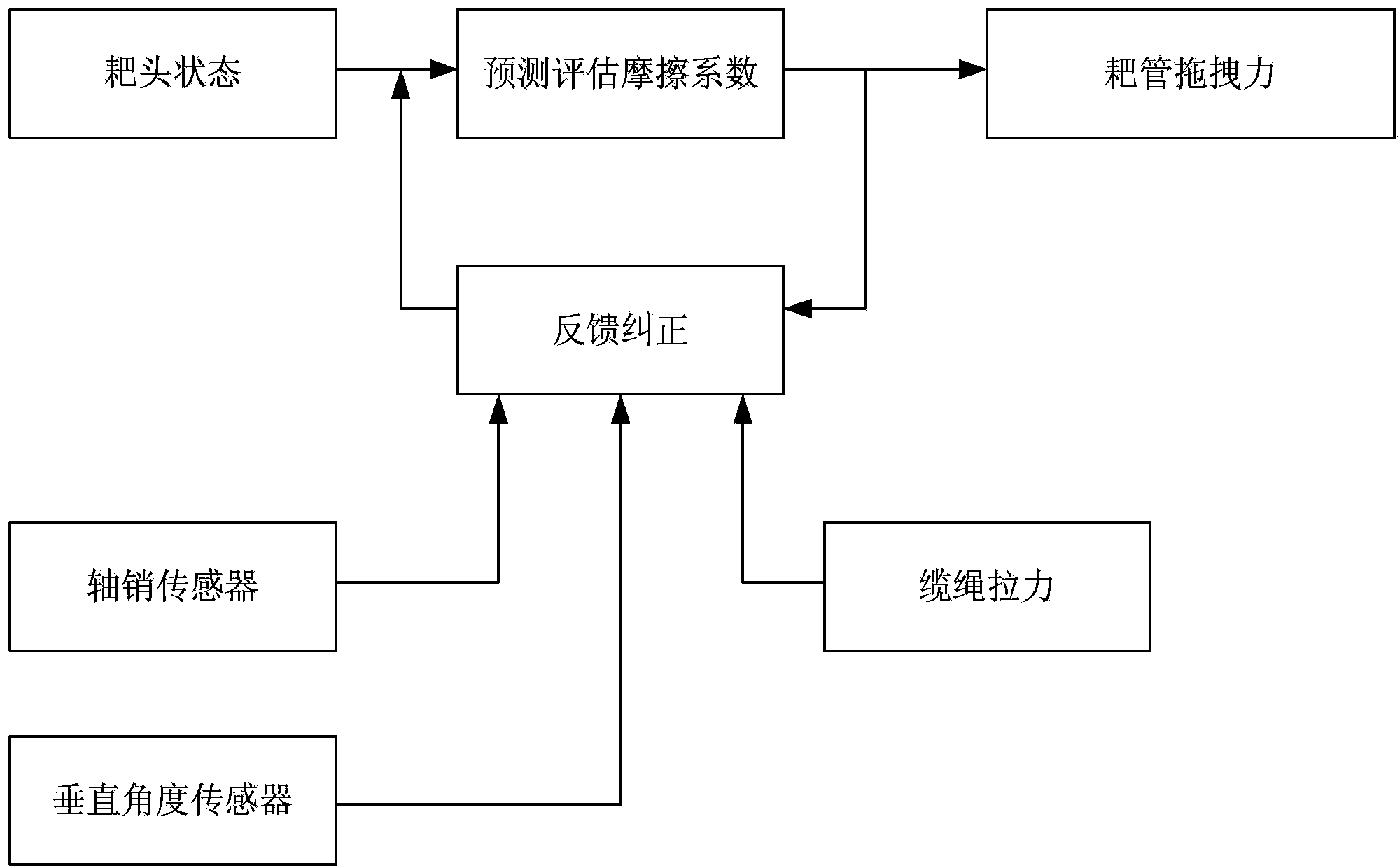
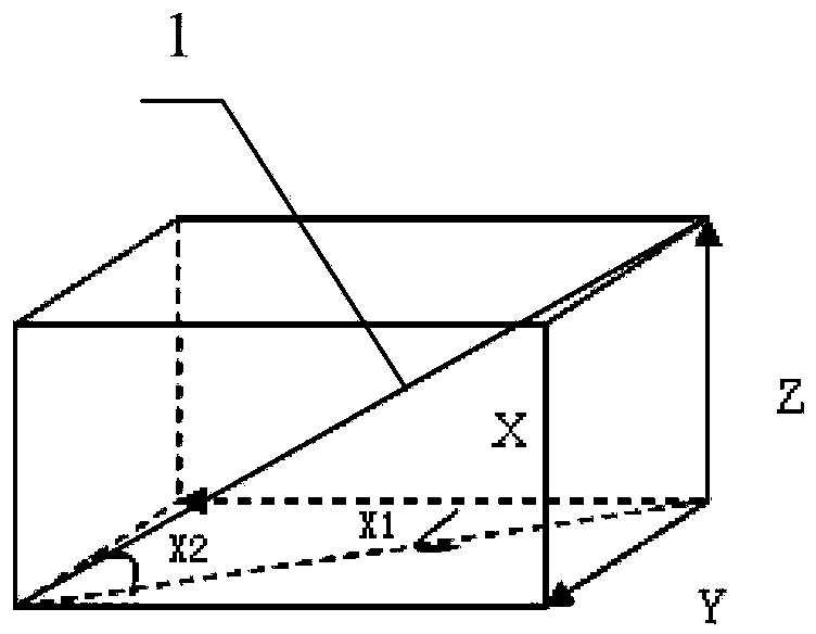
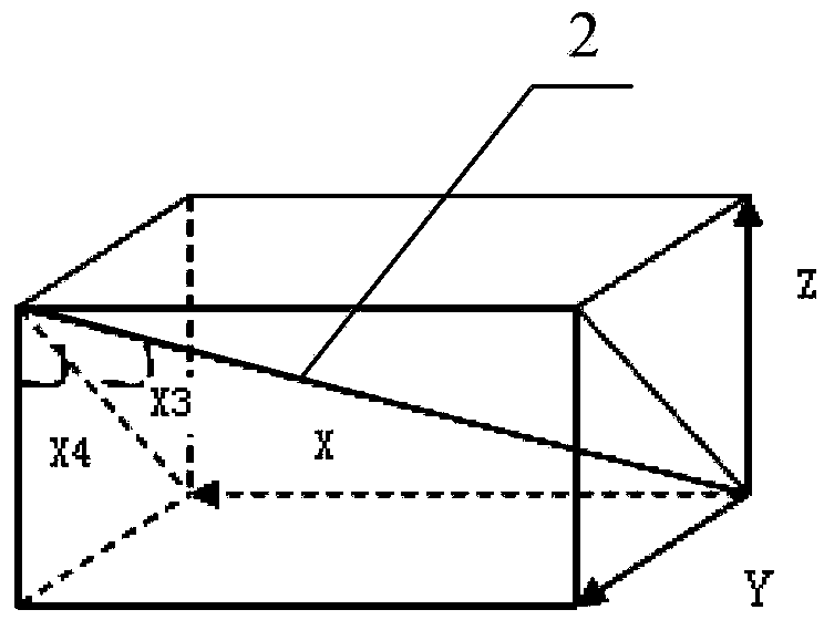
[0029] A method for detecting the dragging force of the rake tube of a trailing suction dredger, through the force balance analysis of the rake head and the rake tube, and the evaluation of the effect of the seabed friction on the rake head during the process of rake suction, how to reduce the drag force of the rake Effective and reasonable estimation of the resistance of the head on the seabed.

[0030] The information collection system of the trailing suction dredger is used to obtain the physical quantities of various evaluation indicators of the raking state, including the pin sensor at the joint of the raking pipe, the angle encoder at the joint of the raking pipe, the angle encoder at the joint of the cable, and the distance between the cable and the pipe. The physical quantity data collected by the force sensor and wave compensator of the rake head.

[0031] The physical quantities obtained by the information collection system of the trailing suction dredger include: th...


PUM


Abstract

The invention relates to a method for testing dragging force of a rake pipe of a trailing suction dredger, and belongs to the field of precision dredging technology. The method for testing the dragging force of the rake pipe of the trailing suction dredger is characterized in that the trailing suction dredger is provided with an information acquisition system, physical quantities of various evaluation indexes of trailing suction states are acquired, and the information acquisition system comprises a hinge pin sensor at a joint of the rake pipe, an angle encoder at a connector of the rake pipe, an angle encoder at a connector of a mooring rope, a force sensor for measuring force exerted by the mooring rope to a rake head of the rake pipe and a wave compensator; and when the dragging force of the rake pipe is tested, stress balance of the rake head and stress balance of the rake pipe are analyzed, the magnitude of action of friction force exerted by a seabed to the rake head is evaluated in a trailing suction procedure, and accordingly decrease of resistance exerted by the seabed to the rake head is effectively estimated. Friction coefficients and positive pressure of the rake head and the seabed are evaluated, the dragging force of the rake pipe of the trailing suction dredger is compensated, accordingly, precision dredging is implemented, and the method has the advantages of convenience in testing, high practicality, wide application range and the like.

Description

technical field [0001] The invention belongs to the technical field of precision dredging, in particular to a method for detecting the dragging force of a dragging tube of a trailing suction dredger. Background technique [0002] At present, trailing suction dredgers have been used more and more widely, especially in the formation of land areas and the construction of coastal industrial parks. Dredging control has the characteristics of high technical content, complex mechanical equipment, and high automation requirements. Accurate dredging becomes an important parameter of dredging index. Since the rake head of the dredger is carried out underwater, it is difficult for the staff to judge the actual working state of the rake head, so it is difficult to improve the high efficiency of mud suction. On the other hand, if there is too much friction between the rake head and the seabed during the rake suction process, it will also have a serious impact on the service life of the...

Claims


Application Information

Patent Timeline
Patent Type & Authority Patents(China)
IPC IPC(8): G01L5/00E02F5/28E02F3/92
Inventor 丁树友顾明田俊峰俞梦蕻袁伟李军戴群王健刘长云杨立楠
Owner CCCC TIANJIN DREDGING
Learn More