A permanent magnet motor

A permanent magnet and unified technology, applied in the direction of magnetic circuits, electrical components, electromechanical devices, etc., can solve problems such as failure to achieve, and achieve the effect of improving electromagnetic torque and reducing torque fluctuations

Active Publication Date: 2016-04-20
GUANGDONG WELLING ELECTRIC MACHINE MFG +1
View PDF7 Cites 0 Cited by
  • Summary
  • Abstract
  • Description
  • Claims
  • Application Information

AI Technical Summary

Problems solved by technology

[0004] How to reduce the cost of the motor on the basis of ensuring the original performance of the motor is an urgent problem to be solved by various companies. Since the cost of permanent magnets accounts for a large proportion of the total cost of the motor, many technical R&D personnel focus on permanent magnets. Considering the cost of the structure and size, but so far have not achieved a satisfactory result

Method used


Image

  • A permanent magnet motor
  • A permanent magnet motor
  • A permanent magnet motor

Examples


Embodiment Construction

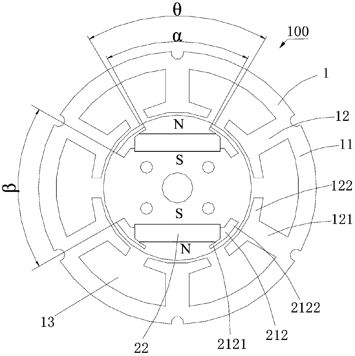
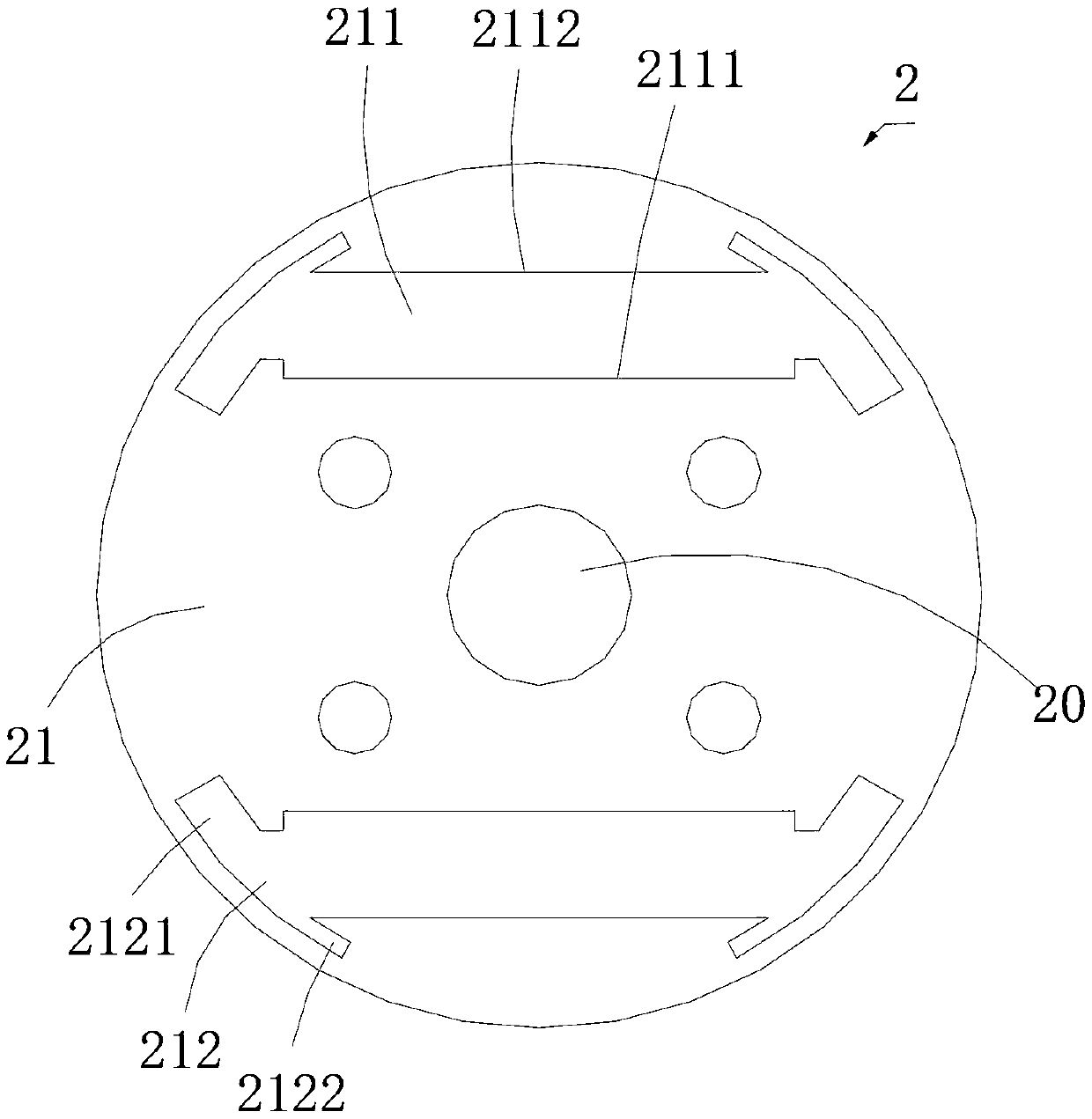
[0020] Please refer to 1 to figure 2 , a permanent magnet motor 100 according to the first embodiment of the present invention, which includes a stator 1 located outside and a rotor 2 located inside the stator 1 .

[0021] In this embodiment, the stator 1 includes an outer edge portion 11 located at the periphery, a plurality of stator teeth 12 extending from the inner surface of the outer edge portion 11 to the center of the outer edge portion 11 , and winding slots 13 between the stator teeth 12 . The outer edge portion 11 is annular, and the stator tooth 12 includes a winding portion 121 connected to the outer edge portion 11 and pole shoes 122 extending from the end of the winding portion 121 to both sides. The stator teeth 12 and winding slots 13 are evenly distributed inside the outer edge portion 11 , and the pitch between two adjacent stator teeth 12 and the slot pitch between two adjacent winding slots 13 are θ degrees. In this embodiment, the number of stator teeth...


PUM


Abstract

A permanent magnet motor comprises a stator (1) and a rotor (2), and the rotor (2) includes: a rotor core (21) having at least two receiving recesses (211), a groove (212) defining a first end (2123) and a second end (2124) formed on each end of each of the receiving recesses (211) and communicated therewith, in which a central angle whose vertex is a center of the rotor core (21) and whose sides pass through the second ends (2124) of the two grooves (212) located on each of the receiving recesses (211) is α, a central angle whose vertex is the center of the rotor core (21) and whose sides pass through the first end (2123) of one groove (212) of one receiving recess (211) and the first end (2123) of one groove (212) of another receiving recess (211) adjacent to the one groove (212) of the one receiving recess (211) is β, and a ratio of α to β ranges from 0.8 to 1.2; and permanent magnets (22) received in the receiving recesses (211) respectively, wherein a magnetic field of any permanent magnet (22) does not cross over other permanent magnets (22).

Description

【Technical field】 [0001] The invention relates to a motor, in particular to a permanent magnet motor. 【Background technique】 [0002] In the prior art, a permanent magnet motor includes a stator and a rotor. The rotor includes a rotor iron core and permanent magnets installed in the rotor iron core. The permanent magnets often use rare earth permanent magnets with high remanence magnetic properties as permanent magnet poles. [0003] See Patent No. CN102171909 and other related patents published on August 31, 2011. The number of permanent magnets in these rotors is four, which are respectively located on the four sides of the rotor core, forming a magnet at the upper and lower ends of the rotor. The opposite pair of permanent magnets, the opposite pair of permanent magnets located at the left and right ends of the rotor, and the permanent magnets at the upper, lower, left and right ends are roughly surrounded by four permanent magnets to form a square structure. According t...

Claims


Application Information

Patent Timeline
Patent Type & Authority Patents(China)
IPC IPC(8): H02K1/27
CPCH02K1/276
Inventor 李节宝陈金涛葛笑诸自强
Owner GUANGDONG WELLING ELECTRIC MACHINE MFG
Why Eureka
Try Eureka