Consequent-pole motor and compressor with same

A technology of alternating poles and polarities, which is applied to electrical components, electromechanical devices, electric components, etc., and can solve problems such as asymmetry, fluctuations, and small reluctance torque between adjacent magnetic poles of alternating pole motors

Active Publication Date: 2018-11-09
GREE ELECTRIC APPLIANCES INC
View PDF6 Cites 2 Cited by
  • Summary
  • Abstract
  • Description
  • Claims
  • Application Information

AI Technical Summary

Problems solved by technology

Therefore, on the one hand, the reluctance of the d-axis magnetic circuit of the alternating pole motor is small, and the inductance of the d-axis is large, resulting in a small difference in inductance between the q-axis and the d-axis, resulting in a small reluctance torque, which limits the increase in electromagnetic torque
On the other hand, due to the thinner equivalent thickness of the permanent magnet, the anti-demagnetization ability drops more obviously
[0006] In addition, due to the asymmetry of adjacent magnetic poles of alternating pole motors, large torque fluctuations are formed during operation

Method used


Image

  • Consequent-pole motor and compressor with same
  • Consequent-pole motor and compressor with same
  • Consequent-pole motor and compressor with same

Examples


Embodiment 1

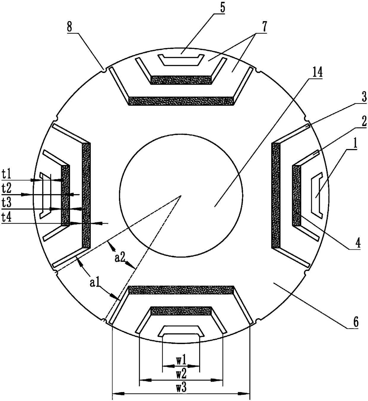
[0041] An alternating pole permanent magnet motor includes a rotor and a stator. figure 1 Shown is the schematic diagram of the rotor structure. There are four sets of slot groups on the rotor, and each set of slot groups is composed of three layers in the radial direction. There is no permanent magnet installed in the slot 1 of the first layer, and the slots (2, 3) of the second layer and the third layer Permanent magnets 4 are installed, and the polarities of all the permanent magnets facing the outer periphery of the rotor are the same polarity, and the sectors where the permanent magnets are located are generally called permanent magnet poles 5 . The soft magnetic material between the different sets of slots is magnetized to the opposite polarity of the permanent magnets, called alternating poles 6 .

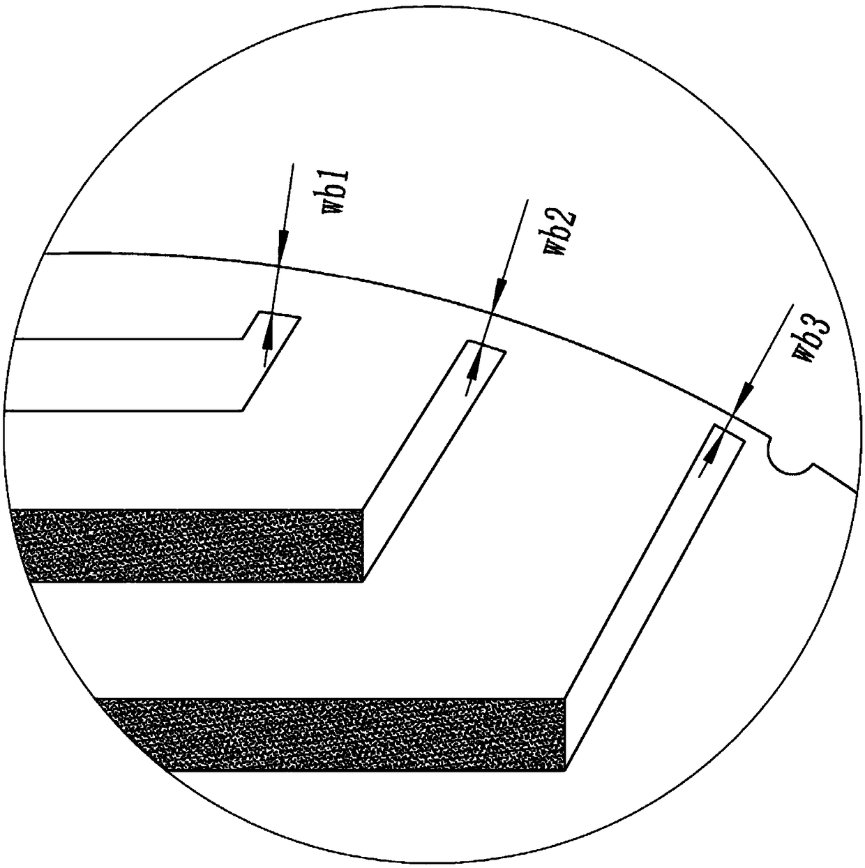
[0042] The slots are arranged in three layers, which can be understood as adding a layer of air slots outside the two layers of permanent magnets, adding such Figure 4 Th...

Embodiment 2

[0065] Permanent magnets are installed in the slots 1 of the first and third layers of the rotor, and no permanent magnets are placed in the slots of the second layer. Other settings are the same as in Example 1.

Embodiment 3

[0067] A compressor comprising the alternating pole motor in Embodiment 1 or 2.


PUM


Abstract

The invention discloses a consequent-pole motor and a compressor with the same. The consequent-pole motor comprises a rotor; the rotor is prepared from a soft magnetic material; one slot groups or more are arranged on the rotor; each slot group is provided with three layers of slots in a radial direction; the slots are divided into first-layer slots, second-layer slots and third-layer slots from the peripheral edge of the rotor to the axle hole of the rotor; permanent magnets are mounted on two layers of slots of each slot group; polarities of the permanent magnets, which face the outer peripheral edge of the rotor, are the same polarities. The motor designed by the invention adopts a multi-layer slot structure, but the permanent magnets are not mounted in all of the slots, so that an inductance Lq of a q axis of the motor can be obviously improved, a difference value of Lq and Ld is increased, an electromagnetic torque of the motor is improved, demagnetization resistance of the rotoris obviously improved, and torque fluctuation is weakened.

Description

technical field [0001] The invention belongs to the technical field of motors, in particular to an alternating pole motor and a compressor having the same. Background technique [0002] A traditional permanent magnet motor, such as an 8-pole permanent magnet motor, has 8 permanent magnets arranged around the center of the rotor along the direction of rotation, and adjacent permanent magnets have different magnetization directions. The alternating pole permanent magnet synchronous motor has only 4 permanent magnets, which are also uniformly distributed along the circumference, and the adjacent permanent magnets have the same length in the magnetization direction. Those with permanent magnet installation slots are called permanent magnet poles. Two permanent magnets are installed The soft magnetic material between the slots is magnetized by the permanent magnet poles to have the opposite polarity to the permanent magnet poles, so it is called an alternating pole permanent magn...

Claims


Application Information

Patent Timeline
IPC IPC(8): H02K1/27H02K1/28
CPCH02K1/276H02K1/28H02K2201/03H02K2213/03
Inventor 李权锋周博肖勇
Owner GREE ELECTRIC APPLIANCES INC
Why Eureka
Try Eureka