Rotor for electric rotating machine

a technology of rotating machine and rotor, which is applied in the direction of dynamo-electric machines, magnetic circuit rotating parts, magnetic circuit shape/form/construction, etc., can solve the problems of ineffective use of iron core regions with limited size or cross-sectional area, and achieve high-torque output efficiently, increase in q-axis inductance, and increase in reactance torque

Inactive Publication Date: 2012-08-09
TOYOTA JIDOSHA KK +2
View PDF0 Cites 35 Cited by
  • Summary
  • Abstract
  • Description
  • Claims
  • Application Information

AI Technical Summary

Benefits of technology

[0017]According to the rotor for an electric rotating machine of the present invention, a q-axis magnetic flux path is formed among the first permanent magnet, the second permanent magnets and the first region, and the central portion of the q-axis magnetic flux path that is formed between the first permanent magnet and the first region and the entrance/exit portions of the q-axis magnetic flux path, which are formed between the second permanent magnets and the second region that are formed on both circumferential sides of the

Problems solved by technology

Another problem is that because the q-axis magnetic flux does not flow smoothly or at all through the generally triangular iron core region 92

Method used


Image

  • Rotor for electric rotating machine
  • Rotor for electric rotating machine
  • Rotor for electric rotating machine

Examples


Embodiment Construction

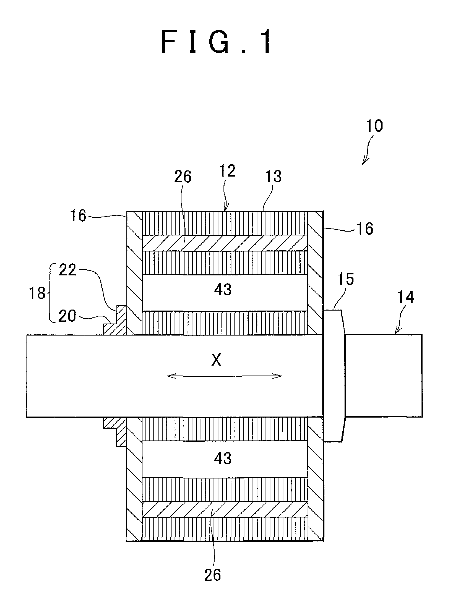
[0023]Description is hereinafter made of an embodiment of the present invention in detail with reference to the accompanying drawings. It should be noted that the specific shapes, materials, numerical values, directions, and so on in this description are examples to facilitate understanding of the present invention, and can be changed as needed depending on the use, purpose, specification, and so on.

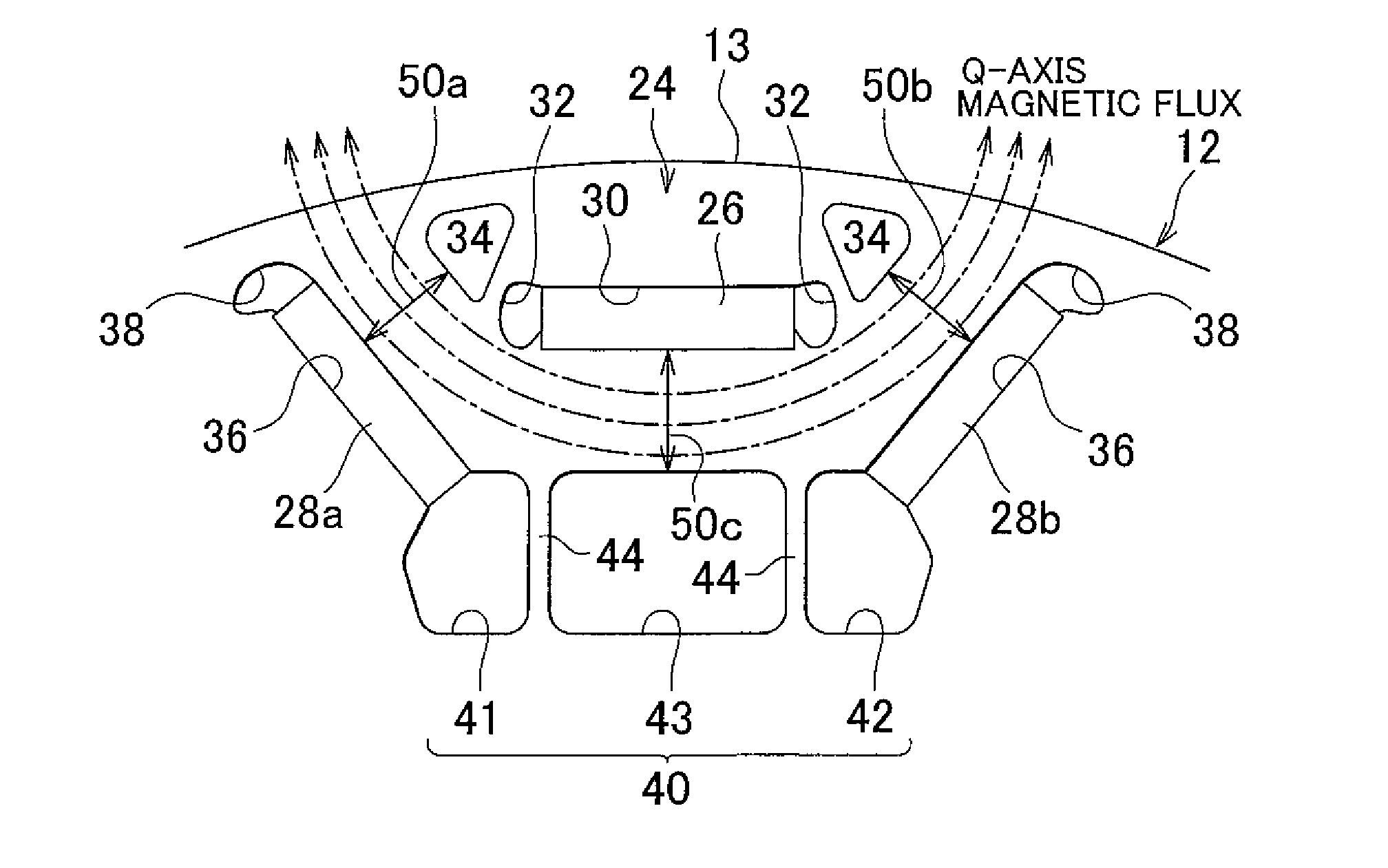
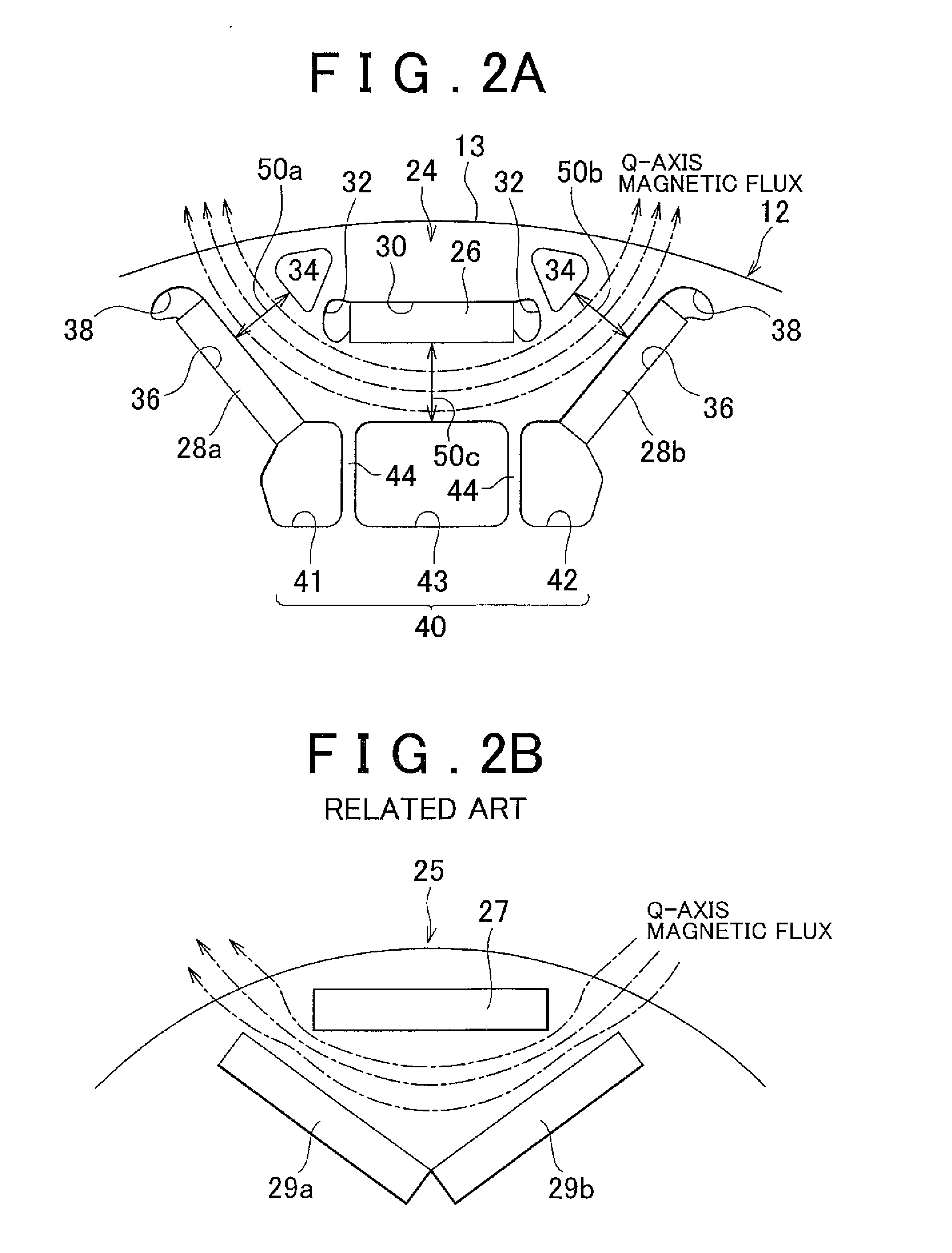
[0024]FIG. 1 is an axial cross-sectional view of a rotor 10 for an electric rotating machine (which may be hereinafter referred to simply as “rotor” as needed) of this embodiment. A cylindrical stator (not shown) is provided around the rotor 10. The stator forms a magnetic field that rotatably drives the rotor 10.

[0025]The rotor 10 includes a columnar or cylindrical columnar iron rotor core 12 that has a central hole, a shaft 14 that fixedly extends through the central hole of the iron rotor core 12, end plates 16 that are disposed in contact with both side of the iron rotor core 12 in t...


PUM


Abstract

An iron rotor core includes a first permanent magnet in an outer peripheral portion of the iron rotor core, second permanent magnets on both circumferential sides of the first permanent magnet and arranged in a generally V-shaped configuration opening radially outward, and a first region provided opposite to the first permanent magnet radially inside the region between the second permanent magnets and having a low magnetic permeability. A q-axis magnetic flux path is formed in an iron core region among the first permanent magnet, the second permanent magnets and the first region, and a central portion thereof is formed between the first permanent magnet and the first region, and entrance/exit portions of the q-axis magnetic flux path formed between the second permanent magnets and second regions provided on both circumferential sides of the first permanent magnet and having a low magnetic permeability with generally the same width.

Description

INCORPORATION BY REFERENCE[0001]The disclosure of Japanese Patent Application No. 2011-021404 filed on Feb. 3, 2011 including the specification, drawings and abstract is incorporated herein by reference in its entirety.BACKGROUND OF THE INVENTION[0002]1. Field of the Invention[0003]The present invention relates to a rotor for an electric rotating machine, and, more particularly, to a rotor for an electric rotating machine that includes a plurality of permanent magnets which are embedded in the outer peripheral portion of an iron rotor core in a circumferentially spaced relationship.[0004]2. Description of the Related Art[0005]As a related art, a rotor 80 for an electric motor as shown in FIG. 3 that is disclosed in Japanese Patent Application Publication No. 2003-134704 (JP-A-2003-134704), for example, is known. FIG. 3 is a diagram that illustrates part of the rotor 80, in other words, one-quarter (90° region) of its cross-section perpendicular to the axis of a shaft 82.[0006]In FIG...

Claims


Application Information

Patent Timeline
IPC IPC(8): H02K1/27
CPCH02K1/2766
Inventor SANO, SHINYATAKEDA, KENINAGAKI, TOMOHIROOTAKE, SHINICHIMIYAJI, TSUYOSHIWATANABE, YUTAYOSHIDA, TOSHIHIKOSAITO, YOICHI
Owner TOYOTA JIDOSHA KK
Why Eureka
Try Eureka