Linear rotation two-degree-of-freedom motor

A degree of freedom, straight line technology, applied in the field of electric motors, can solve the problems of inconvenient use, large installation space, large volume, etc., and achieve the effect of convenient installation and use process, increased current, and reduced volume

Active Publication Date: 2021-06-18
横川机器人(深圳)有限公司
View PDF4 Cites 3 Cited by
  • Summary
  • Abstract
  • Description
  • Claims
  • Application Information

AI Technical Summary

Problems solved by technology

[0003] In view of the related technologies mentioned above, the inventor believes that although the two-degree-of-freedom drive can be realized in a combined manner, the overall volume is relatively large, so that a larger installation space needs to be reserved during installation and use, which leads to the process of use more inconvenient

Method used


Image

  • Linear rotation two-degree-of-freedom motor
  • Linear rotation two-degree-of-freedom motor
  • Linear rotation two-degree-of-freedom motor

Examples


Embodiment 1

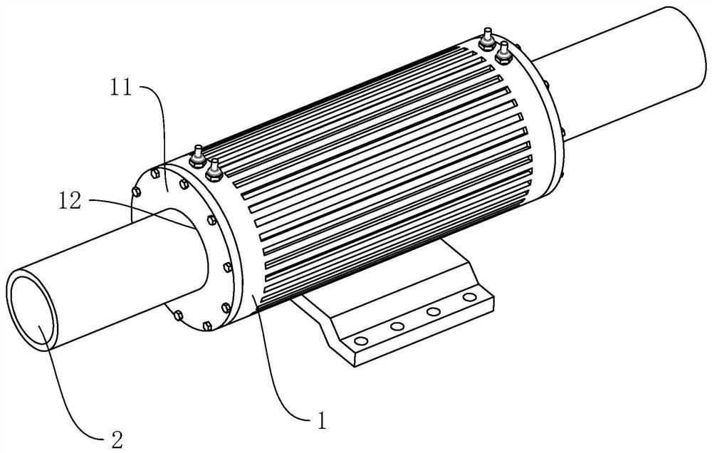
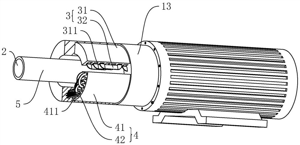
[0038] A linear rotation two-degree-of-freedom motor disclosed in the present application, such as figure 1 and figure 2 As shown, it includes a tubular base 1, a main shaft 2 passing through the base 1, a first driving member 3 that drives the main shaft 2 to move along its axis, and a second driving member 4 that drives the main shaft 2 to rotate along its axis. 2 is the magnetic guide tube. Both ends of the base 1 are detachably connected by bolts with end caps 11 capable of closing the openings at both ends. The end caps 11 are coaxially provided with guide holes 12, and the main shaft 2 is passed through the guide holes 12, and the side of the main shaft 2 The wall is attached to the inner wall of the guide hole 12 , and both ends of the main shaft 2 extend from both ends of the base 1 . Both the first driver 3 and the second driver 4 are arranged in the base 1. The first driver 3 includes a first iron core 31 and a first winding 32 wound around the first iron core 31....

Embodiment 2

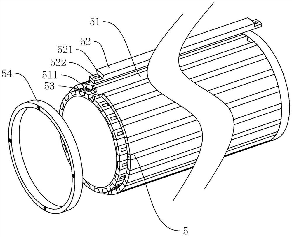
[0044] Such as image 3 As shown, the difference from Embodiment 1 is that the outer wall of the conductive tube 5 is provided with a plurality of driving grooves 51 in the circumferential direction, and the driving grooves 51 penetrate the two ends of the main shaft 2. At this time, when the second driving member 4 is energized, the magnetic induction The wires can be gathered at the position where the main shaft 2 does not have a drive slot 51. At this time, the main shaft 2 rotates one by one during the rotation process, so that the torsion of the main shaft 2 is greater.

[0045] Such as image 3 As shown, after the drive slot 51 is opened, the main shaft 2 will rotate one by one according to the radian occupied by the drive slot 51 when the main shaft 2 rotates, so that the stepless control of the main shaft 2 cannot be realized, so the drive slot 51 is also embedded A detachable filling strip 52 is provided, the length of the filling strip 52 is equal to the length of t...


PUM


Abstract

The invention relates to a linear rotation two-degree-of-freedom motor. The linear rotation two-degree-of-freedom motor comprises a base, a main shaft, a first driving part and a second driving part; the first driving part comprises a first iron core arranged in the base and a first winding wound on the first iron core, and the winding direction of the first winding is perpendicular to the axis of the main shaft; the second driving part comprises a second iron core arranged in the base and a second winding wound on the second iron core, and the winding direction of the second winding is parallel to the axis of the main shaft; the main shaft penetrates through the base, the two ends of the main shaft extend out of the two ends of the base, magnetic induction lines of the first driving part and the second driving part penetrate through the main shaft, and the distance between the first winding and the main shaft is equal to the distance between the second winding and the main shaft. According to the linear rotation two-degree-of-freedom motor, the first driving part and the second driving part are arranged to directly drive the main shaft to move, and at the moment, the sizes of the first driving part and the second driving part can be reduced, so that the overall size of the linear rotation two-degree-of-freedom motor is reduced, and the linear rotation two-degree-of-freedom motor is more convenient to install and use.

Description

technical field [0001] The present application relates to the technical field of motors, in particular to a linear rotation two-degree-of-freedom motor. Background technique [0002] As the complexity of industrial drive systems increases and the drive precision requirements increase, the application of two-degree-of-freedom drives is becoming more and more extensive. The current two-degree-of-freedom drive is usually realized through a combined structure, that is, by setting a first driving member that drives the main shaft to move linearly, and then setting a second driving member that drives the first driving member to rotate along the axis of the main shaft, so as to realize The driven main shaft can not only rotate along its axis, but also move along its axis. [0003] In view of the related technologies mentioned above, the inventor believes that although the two-degree-of-freedom drive can be realized in a combined manner, the overall volume is relatively large, so t...

Claims


Application Information

Patent Timeline
Patent Type & Authority Applications(China)
IPC IPC(8): H02K16/00H02K41/02
CPCH02K16/00H02K41/02
Inventor 王书华王建云刘步军
Owner 横川机器人(深圳)有限公司
Why Eureka
Try Eureka