
Rotor of motor, driving motor and vehicle

A technology of rotors and rotor cores, applied in the direction of electric components, magnetic circuit rotating parts, electrical components, etc., can solve the problems of small output torque, limit the application of motors, and cannot make full use of reluctance torque to achieve electromagnetic torque High, large air gap magnetic density, small magnetic flux leakage effect

Pending Publication Date: 2021-03-30
ANHUI WELLING AUTO PARTS CO LTD
View PDF0 Cites 2 Cited by
  • Summary
  • Abstract
  • Description
  • Claims
  • Application Information

AI Technical Summary

Problems solved by technology

However, the motor rotor in the related art cannot make full use of the reluctance torque, and the output torque is small, which limits the application of the motor

Method used


Image

  • Rotor of motor, driving motor and vehicle
  • Rotor of motor, driving motor and vehicle
  • Rotor of motor, driving motor and vehicle

Examples


Embodiment Construction

[0041] Embodiments of the present invention are described in detail below, examples of which are shown in the drawings, wherein the same or similar reference numerals designate the same or similar elements or elements having the same or similar functions throughout. The embodiments described below by referring to the figures are exemplary only for explaining the present invention and should not be construed as limiting the present invention.

[0042]In describing the present invention, it should be understood that the terms "center", "longitudinal", "transverse", "length", "width", "thickness", "upper", "lower", "front", " Back", "Left", "Right", "Vertical", "Horizontal", "Top", "Bottom", "Inner", "Outer", "Clockwise", "Counterclockwise", "Axial" , "radial", "circumferential" and other indicated orientations or positional relationships are based on the orientations or positional relationships shown in the drawings, which are only for the convenience of describing the present i...


PUM


Abstract

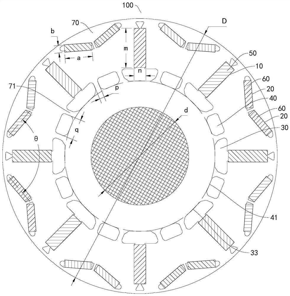
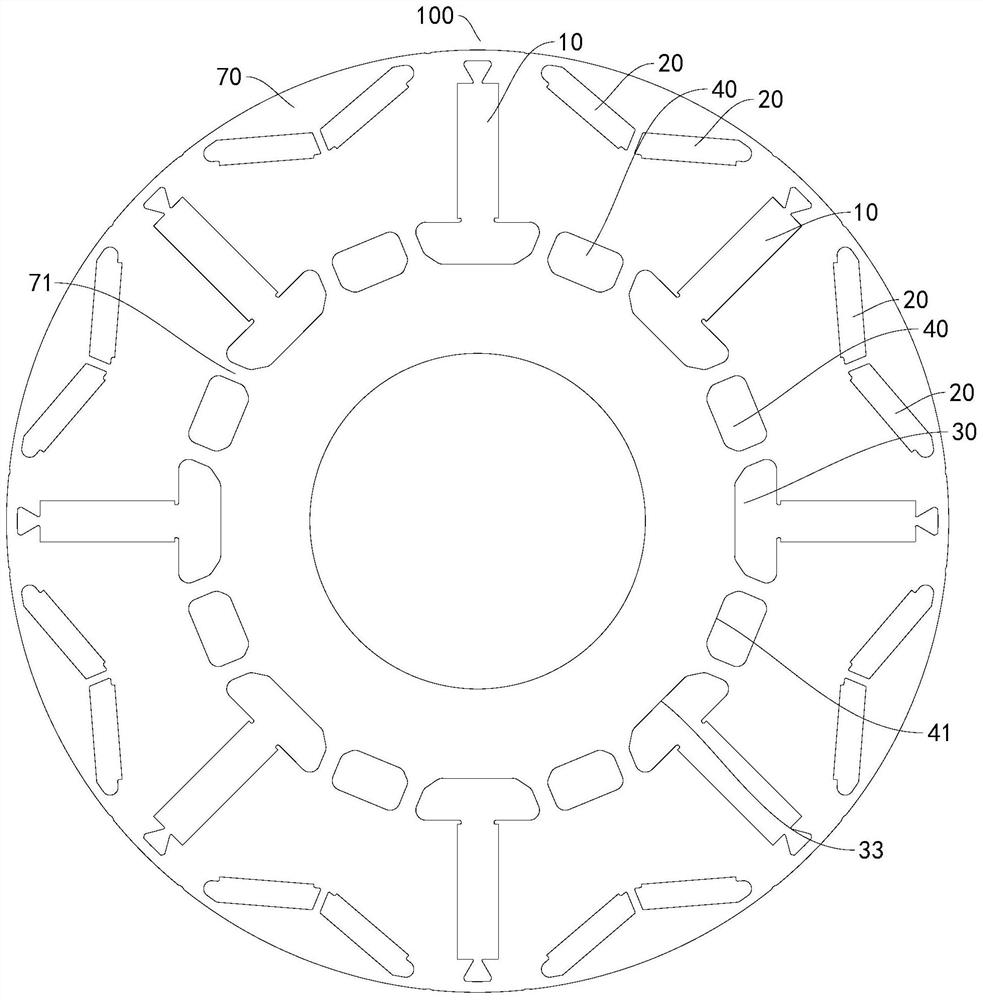
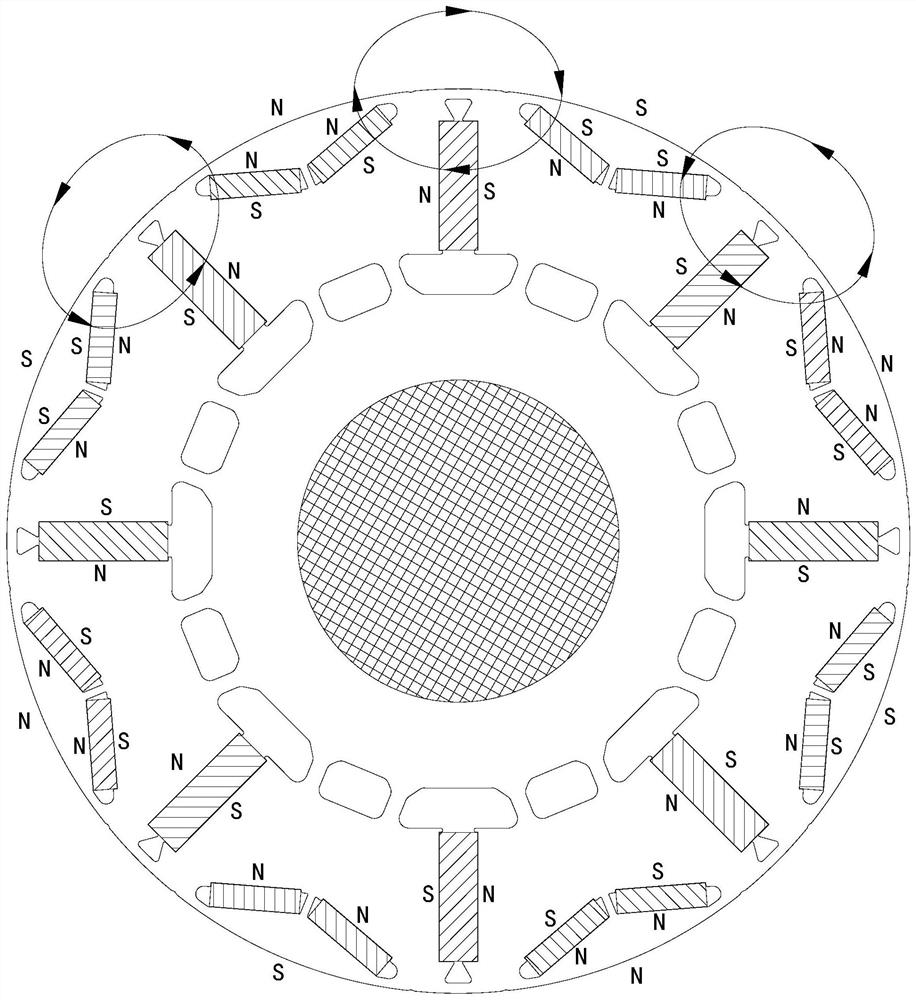
The invention discloses a rotor of a motor, a driving motor and a vehicle. The rotor comprises a rotor core; a plurality of first permanent magnets and a plurality of second permanent magnets which are installed on the rotor core, wherein the plurality of first permanent magnets extend along the radial direction of the rotor core and are distributed at intervals along the circumferential directionof the rotor core, and two second permanent magnets are arranged between two adjacent first permanent magnets; the radial inner ends of the two second permanent magnets located between every two adjacent first permanent magnets are close to each other, the radial outer ends of the two second permanent magnets located between every two adjacent first permanent magnets are far away from each other,the sectional area of each first permanent magnet is S1, and the sectional area of each second permanent magnet is S2. According to the rotor provided by the embodiment of the invention, the spoke type permanent magnet formed by the first permanent magnet and the V-shaped permanent magnet formed by the two second permanent magnets are designed in a composite mode, so the rotor has the advantagesof being small in magnetic flux leakage, good in demagnetization resistance, large in air gap flux density and the like, the optimal matching of permanent magnet torque and reluctance torque is achieved, and the motor is high in electromagnetic torque and good in torque performance and weak magnetic performance.

Description

technical field [0001] The present invention relates to the technical field of motors, and more specifically, to a rotor of a motor, a driving motor and a vehicle. Background technique [0002] Due to the existence of reluctance torque, the built-in permanent magnet synchronous motor can achieve an increase in torque density and an effective expansion of the operating range in the constant power region. However, the motor rotor in the related art cannot make full use of the reluctance torque, and the output torque is small, which limits the application of the motor. Contents of the invention [0003] The present invention aims to solve at least one of the technical problems existing in the prior art. Therefore, an object of the present invention is to provide a rotor of an electric motor, which improves the electromagnetic torque and realizes the optimal cooperation of the permanent magnet torque and the reluctance torque. [0004] Another object of the present invention...

Claims


Application Information

Patent Timeline
Patent Type & Authority Applications(China)
IPC IPC(8): H02K1/27
CPCH02K1/2766H02K2213/03H02K2201/03
Inventor 顾正雍方亮陈金涛
Owner ANHUI WELLING AUTO PARTS CO LTD
Learn More