Rotor assembly and alternating pole motor

A technology of alternating poles and components, applied in electric components, magnetic circuit rotating parts, electrical components, etc., can solve problems such as torque drop and affecting motor performance.

Pending Publication Date: 2019-10-25
GREE ELECTRIC APPLIANCES INC
View PDF0 Cites 3 Cited by
  • Summary
  • Abstract
  • Description
  • Claims
  • Application Information

AI Technical Summary

Problems solved by technology

When the magnetic flux area of ​​the permanent magnet is designed too large, the magnetic force line will...

Method used


Image

  • Rotor assembly and alternating pole motor
  • Rotor assembly and alternating pole motor
  • Rotor assembly and alternating pole motor

Examples


Embodiment Construction

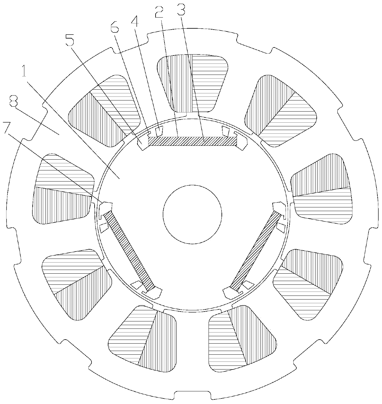
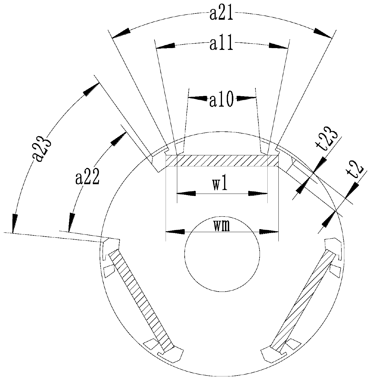
[0031] see in conjunction Figure 1 to Figure 9 As shown, according to the embodiment of the present application, the rotor assembly includes a rotor core 1, the rotor core 1 includes permanent magnet poles and alternate poles arranged alternately along the circumferential direction, the permanent magnet poles include installation slots 2, and permanent magnet poles are installed in the installation slots 2. The magnet 3, the polarity of the permanent magnet 3 facing the outer periphery of the rotor core 1 is the same polarity, the two ends of the installation groove 2 are respectively provided with the second air groove 5, and the two sides of the magnetic pole center line are respectively provided with the first air groove 4 , the first air slot 4 is located between the second air slot 5 and the center line of the magnetic pole on the side close to the second air slot 5, between the radially outer side wall of the first air slot 4 and the first slot wall near the center line ...


PUM


Abstract

The invention provides a rotor assembly and an alternating pole motor. The rotor assembly includes a rotor core (1), wherein the rotor core (1) includes permanent magnetic poles and alternating polesalternately arranged in the circumferential direction, the permanent magnet poles include mounting grooves (2), permanent magnets (3) are mounted in the mounting grooves (2), polarities of the permanent magnets (3) facing the outer circumference of the rotor core (1) are of the same polarity, second air grooves (5) are respectively disposed at both ends of the mounting grooves (2), first air grooves (4) are disposed on two sides of magnetic pole center lines, the first air grooves (4) are located on a side between the second air grooves (5) and the magnetic pole center lines adjacent to the second air grooves (5), an acute angular tip is formed between a radial outer sidewall of the first air grooves (4) and a first groove wall adjacent to the magnetic pole center lines, and the acute angular tip is gathered toward the magnetic pole center lines. The rotor assembly is advantaged in that the electromagnetic torque drop caused by the excessive magnetic flux area of the permanent magnetscan be effectively suppressed, and motor performance is improved.

Description

technical field [0001] The present application relates to the technical field of motors, in particular to a rotor assembly and an alternating pole motor. Background technique [0002] The number of permanent magnets used by the alternating pole permanent magnet synchronous motor is only half of that of the traditional permanent magnet synchronous motor. Therefore, it can fully utilize the permanent magnets, which can significantly reduce the amount of permanent magnets used, thereby reducing the cost of the motor. [0003] However, its special magnetic circuit structure also brings many problems, including the decrease of output torque caused by the reduction in the use of permanent magnets, and the problem of increased torque fluctuation caused by the asymmetry of adjacent magnetic pole structures, which limits the further promotion of alternating pole motors. application. [0004] In the general motor design process, the traditional concept is that the fewer air slots exi...

Claims


Application Information

Patent Timeline
IPC IPC(8): H02K1/27H02K21/02
CPCH02K1/2766H02K21/02H02K2213/03H02K1/2746
Inventor 胡余生李权锋丁佳婷桂鹏千史进飞
Owner GREE ELECTRIC APPLIANCES INC
Why Eureka
Try Eureka