
Rotor component and permanent magnet motor

A component and rotor technology, applied in the direction of electric components, magnetic circuit rotating parts, magnetic circuits, etc., can solve the problems of motor performance degradation, effect reduction, motor output torque reduction, etc.

Active Publication Date: 2019-11-01
GREE ELECTRIC APPLIANCES INC
View PDF7 Cites 2 Cited by
  • Summary
  • Abstract
  • Description
  • Claims
  • Application Information

AI Technical Summary

Problems solved by technology

[0003] However, it has been found through research that although the torque ripple can be reduced in the prior art, more air gaps on the pole pieces will weaken the amplitude of the air gap flux density, resulting in a significant drop in the output torque of the motor, resulting in a decline in the motor's operating performance
On the other hand, the number, shape, and position of slots are closely related to the structure of the rotor. When the rotor structure of the motor changes, its effect will be reduced or even counterproductive.

Method used


Image

  • Rotor component and permanent magnet motor
  • Rotor component and permanent magnet motor
  • Rotor component and permanent magnet motor

Examples


Embodiment Construction

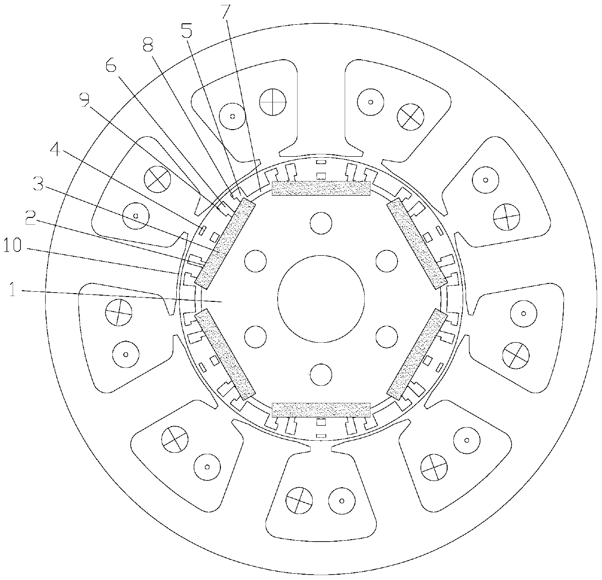
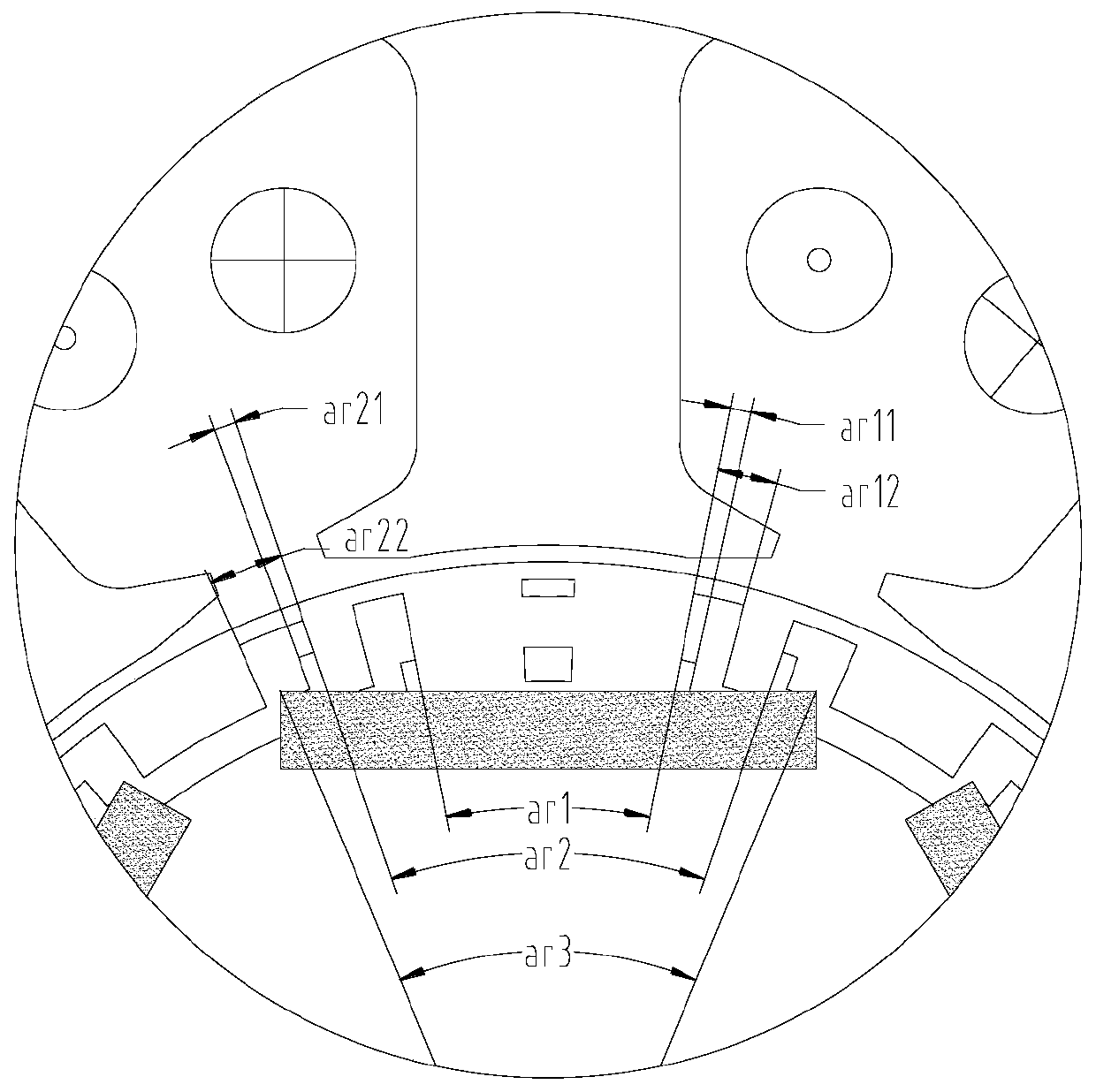
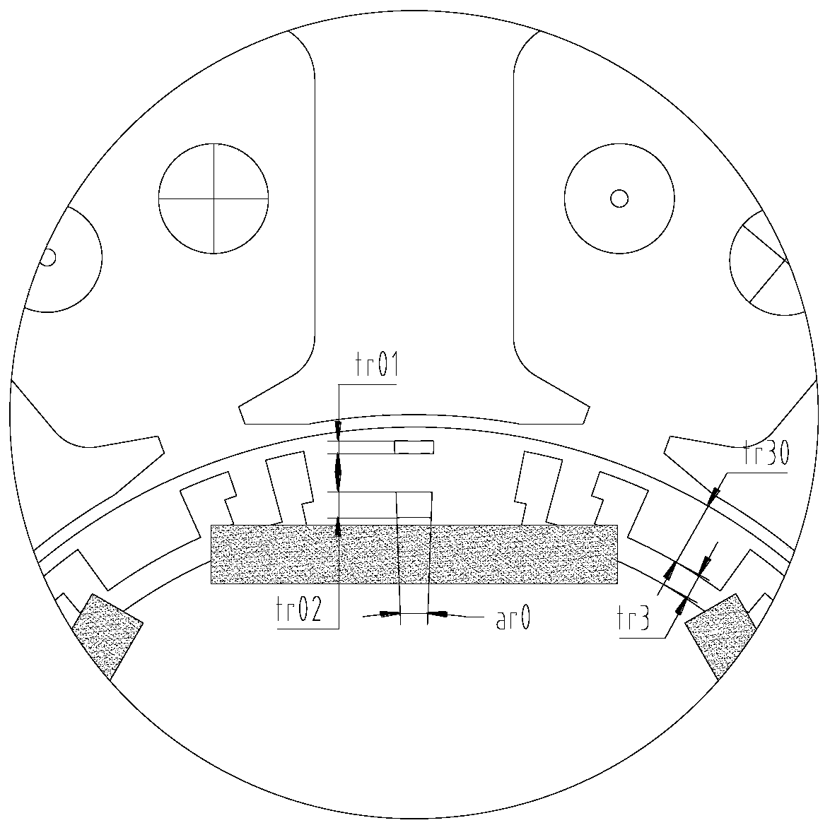
[0035] see in conjunction Figure 1 to Figure 9 As shown, according to the embodiment of the present application, the rotor assembly includes a rotor core 1, a mounting groove 2 is arranged on the rotor core 1 along the circumferential direction, a permanent magnet 3 is installed in the mounting groove 2, and a first The two ends of the air slot 4 and the mounting slot 2 are respectively provided with a second air slot 5 , and a third air slot 6 is provided between the center line of the magnetic pole and the second air slot 5 near the second air slot 5 . For the convenience of description, the following embodiments are described by taking the structure of the same permanent magnetic pole as an example.

[0036] Compared with the radially extending slot structure of the rotor pole shoes in the prior art, the structure of the air slot is improved in this application. The first air slot 4 is set at the position of the center line of the magnetic pole. Both sides are provided wi...


PUM


Abstract

The application provides a rotor component and a permanent magnet motor. The rotor component includes a rotor core (1), a mounting grooves (2) are disposed on the rotor core (1) in a circumferential direction, permanent magnets (3) are mounted in the mounting grooves (2), first air grooves (4) are arranged on the center line of a magnetic pole, the two ends of the mounting grooves (2) are respectively provided with second air grooves (5), and third air grooves (6) are arranged at one side, close to the second air grooves (5), between the center line of the magnetic pole and the second air grooves (5). The rotor component can greatly reduce the torque fluctuation of the permanent magnet motor during operation on the premise of ensuring the electromagnetic torque of the motor.

Description

technical field [0001] The present application relates to the field of motor technology, in particular to a rotor assembly and a permanent magnet motor. Background technique [0002] Torque fluctuation is an inherent characteristic of the motor, which increases the torque fluctuation during the operation of the motor, thereby causing the vibration and operating noise of the motor to increase. The main pole magnetic field of the rotor is generally a non-strict sinusoidal magnetic field, which contains some harmonics, and when the motor load is running, due to the armature reaction, the flux density waveform will further deteriorate, the harmonic distortion rate will increase, and the motor torque fluctuation will increase. How to weaken the permanent magnet motor Torque ripple is an industry problem. An effective measure is to open some slots on the pole piece of the rotor to weaken the armature reaction of the motor, thereby reducing the air gap flux density distortion rate...

Claims


Application Information

Patent Timeline
Patent Type & Authority Applications(China)
IPC IPC(8): H02K1/27H02K29/03
CPCH02K1/274H02K29/03H02K2201/03H02K2213/03
Inventor 李权锋何琛颐史进飞
Owner GREE ELECTRIC APPLIANCES INC
Learn More