Power quality compound compensation method

A compensation method and power quality technology, applied in reactive power compensation, reactive power adjustment/elimination/compensation, AC network to reduce harmonics/ripples, etc. Governance technology simplification and other issues to achieve the effect of solving single function and improving cost performance

Active Publication Date: 2013-05-29
JIANGSU WEIFAN INTELLIGENT ELECTRICAL TECH
View PDF4 Cites 5 Cited by
  • Summary
  • Abstract
  • Description
  • Claims
  • Application Information

AI Technical Summary

Problems solved by technology

[0007] The purpose of the present invention is to provide a composite compensation method for power quality, which can overcome the defects of the existing single power quality control technology. Optimum compensation can effectively solve the problem of large equipment investment and large floor area

Method used


Image

  • Power quality compound compensation method

Examples


Embodiment Construction

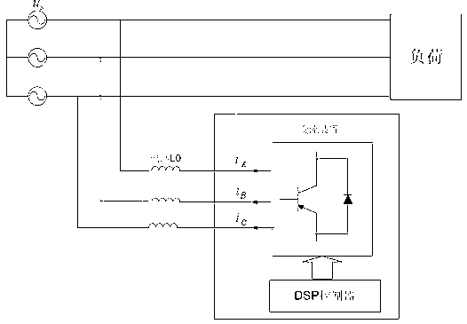
[0018] A method for compound compensation of power quality, comprising the steps of:

[0019] 1) Sampling the current grid voltage signal, load current signal and compensation current signal of the compensation device;

[0020] 2) Select different command current calculation methods according to different compensation methods. The first compensation method is reactive power and fixed-order harmonic compensation; the second compensation method is reactive power and harmonic compensation. When the first compensation method is selected In the compensation mode, the phase-locked loop is used to extract the synchronous angular frequency of the grid voltage signal, and the synchronous angular frequency wt is used to perform dq transformation on the load current in step 1), to obtain the AC active current component and the AC reactive current component, and the AC reactive current component The current component passes through a low-pass filter to obtain the fundamental reactive powe...


PUM


Abstract

The invention relates to a power quality compound compensation method which includes the steps: sampling a voltage signal and a load current signal of a current power grid and a compensation current signal of a compensation device; and selecting different directive current calculation methods according to different compensation modes. The first compensation mode is a reactive power and rating harmonic compensation mode, and the second compensation mode is a reactive power and harmonic compensation mode. When the first compensation mode is selected, a fundamental reactive power compensation current component is firstly calculated, directive harmonic current is then calculated, and compound compensation directive current needed by the first compensation mode is obtained by adding the fundamental reactive power compensation current component and the directive harmonic current. When the second compensation mode is selected, a fundamental active current component is firstly obtained and subtracted from load current to obtain compound compensation directive current in the second compensation mode. By the power quality compound compensation method, reactive power and harmonic are controlled in a compound manner, the shortcoming of single function of a power quality control device at present is overcome, and the cost performance of the power quality control device is improved.

Description

technical field [0001] The invention belongs to the field of compound control of electric energy quality, and in particular relates to a control method of comprehensive reactive power compensation technology and harmonic control technology. Background technique [0002] Electric energy is an important material guarantee for the rapid development of social economy. In recent years, various electric power users have higher and higher requirements for electric energy quality, and pay more and more attention to various quality problems in the process of electric energy application. The usual power quality problems are mainly caused by various reactive loads, unbalanced loads and nonlinear loads. These devices not only consume a large amount of reactive power during operation, but also generate a large number of harmonics, causing the grid voltage to fluctuate violently. Reduce the efficiency of grid use, seriously affect the quality of grid power supply, and cause users connecte...

Claims


Application Information

Patent Timeline
Patent Type & Authority Applications(China)
IPC IPC(8): H02J3/18H02J3/01
CPCY02E40/30Y02E40/40
Inventor 邹积勇黄秋燕杨立军杨志薛恒怀
Owner JIANGSU WEIFAN INTELLIGENT ELECTRICAL TECH
Why Eureka
Try Eureka