Method and arrangement for polarization control in a communication system

A technology of user equipment and polarization state, which is applied in the field of communication systems, can solve problems such as incomplete suppression and negative communication quality, and achieve the effect of suppressing inter-cell interference

Active Publication Date: 2013-06-05
TELEFON AB LM ERICSSON (PUBL)
View PDF10 Cites 2 Cited by
  • Summary
  • Abstract
  • Description
  • Claims
  • Application Information

AI Technical Summary

Problems solved by technology

Even state of the art MMSE receivers will not be able to fully suppress this interference
Therefore, for UEs, hereinafter referred to as legacy users, that demodulate

Method used


Image

  • Method and arrangement for polarization control in a communication system
  • Method and arrangement for polarization control in a communication system
  • Method and arrangement for polarization control in a communication system

Examples


Embodiment Construction

[0032] Throughout the drawings, the same reference numbers are used for similar or identical elements. Although this disclosure primarily deals with and describes the case of horizontal and vertical polarization states, the same approach can be applied to other orthogonal polarization states without departing from the main purpose of this disclosure.

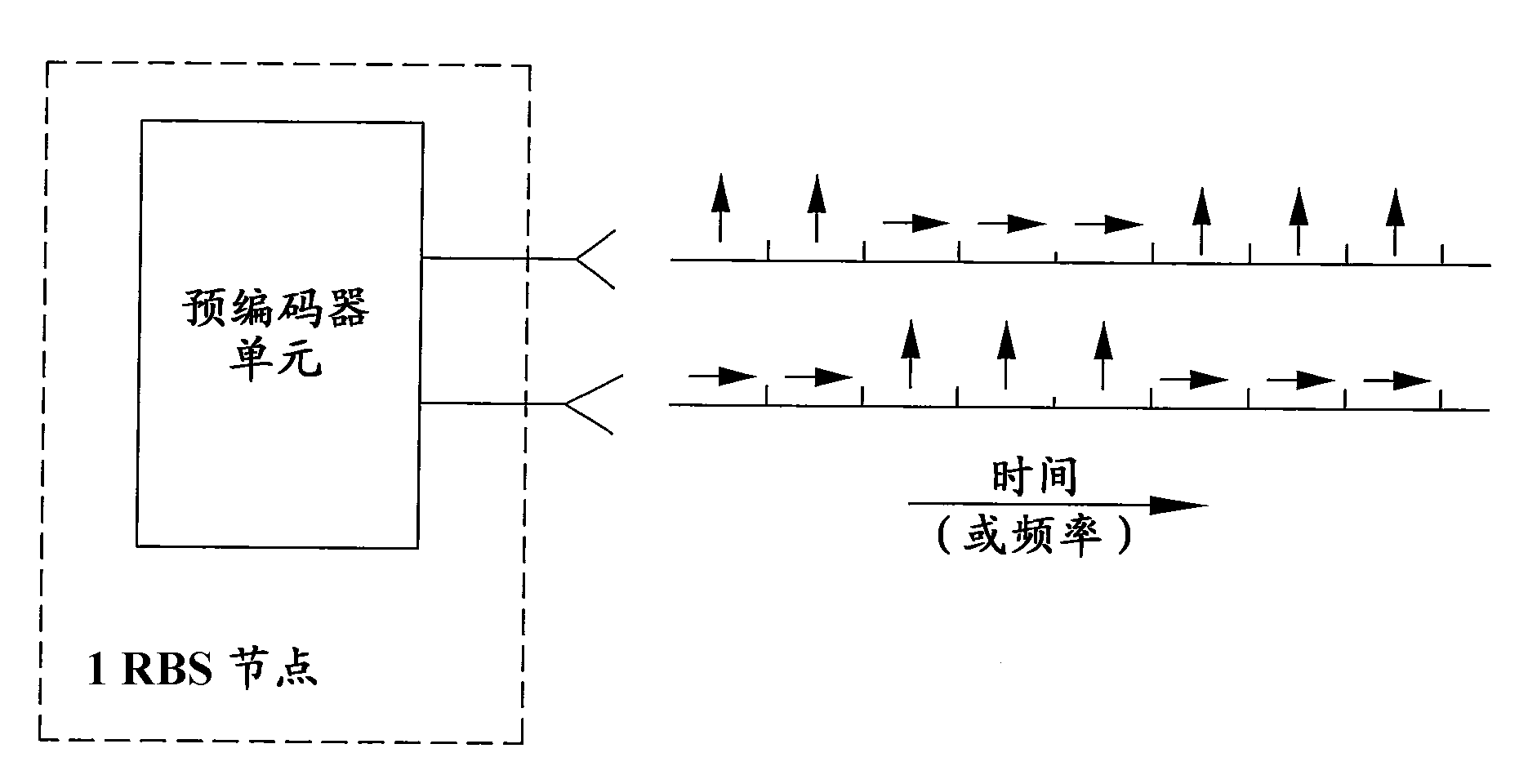
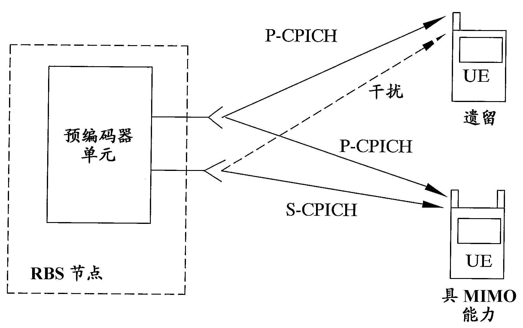
[0033] A recent development for balancing power between the power amplifiers associated with each of the two transmit antennas in MIMO capable devices in WCDMA / HSPA systems, and enabling legacy UEs to benefit from the total available power involves common precoders The introduction of (see Figure 5 ). The precoder distributes each signal to be transmitted with equal amplitude across the two power amplifiers. When used in combination with cross-polarized transmit antennas, this will result in a transmitted polarization that is a linear combination of the polarizations of the two antennas. The phase shift between the two anten...


PUM


Abstract

Controlling the polarization state of signals to be transmitted from a MIMO capable radio base station node to a plurality of user equipment, which radio base station node comprises a precoder unit connecting a first and a second virtual antenna port to a respective first and second transmit antenna port, by the steps of controlling (S10) a relative phase between transmitted signals from the first and second transmit antenna port to provide a predetermined pair of orthogonal polarization states for signals transmitted on the first and second virtual antenna ports, and interchanging (S20) the polarization states of the first and second virtual antenna ports, to provide transmitted polarized signals with alternating polarization states.

Description

technical field [0001] The present disclosure relates generally to communication systems and, in particular, to polarization state control for signals transmitted in such systems. Background technique [0002] The introduction of MIMO capability in existing WCDMA HSPA networks is an important step in the evolution of the technology towards higher spectral efficiency and bit rates. With MIMO, at least two transmit antennas are used within the same cell. However, the introduction of a second transmit antenna port has a negative impact on legacy user equipment (UE), as figure 1 As shown, for legacy user equipment, the signal transmitted on the second antenna port will appear as interference. Ideally, since second antenna port signals such as S-CPICH and MIMO streams are transmitted with channelization codes (which are orthogonal to the codes used for legacy users), this interference would be perfectly orthogonal and thus fully suppressed . However, code orthogonality is onl...

Claims


Application Information

Patent Timeline
IPC IPC(8): H04B7/04H04B7/06H04B7/10
CPCH04B7/0413H04B7/0469H04B7/0615H04B7/0473H04B7/10
Inventor H.阿斯普伦B.哈格曼F.奥维斯约A.赖亚尔
Owner TELEFON AB LM ERICSSON (PUBL)
Why Eureka
Try Eureka