

Injection solution distribution box and injection solution distributor provided with the same
A dispensing box and dispensing machine technology, applied in the field of medical device manufacturing, can solve problems such as fragile injections
- Summary
- Abstract
- Description
- Claims
- Application Information
AI Technical Summary
Problems solved by technology
Method used
Image

Examples
Embodiment Construction
[0024] The present invention will be described in detail below in conjunction with specific embodiments shown in the accompanying drawings. However, these embodiments do not limit the present invention, and any structural, method, or functional changes made by those skilled in the art according to these embodiments are included in the protection scope of the present invention.
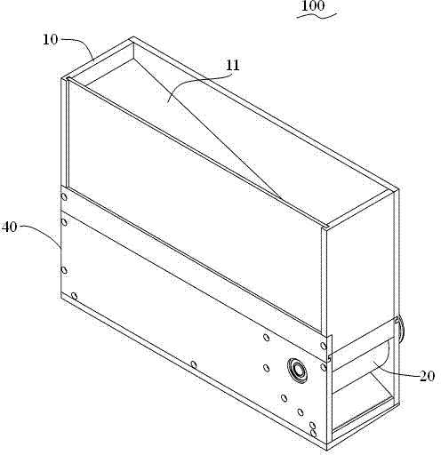
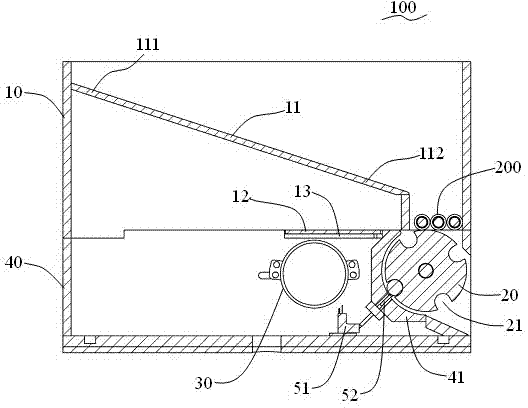
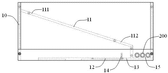
[0025] ginseng Figure 1 to Figure 4 , to introduce a specific embodiment of the injection dispensing box 100 provided by the present invention. In this embodiment, the injection dispensing box 100 includes a box body 10 , a transmission plate 11 , a dial 20 , and a driving mechanism 30 .
[0026] The box body 10 is used for accommodating the injection 200, and there is a drug outlet 15 on it. The transmission plate 11 is installed in the box body 10. The transmission plate 11 is used to move the injection 200 to the drug outlet 15, and the drug outlet The port 15 is preferably provided at the bottom ...
PUM
 Abstract
Description
Claims
Application Information