Elevator system and elevator control method
A technology of elevator system and elevator control device, which is applied in the direction of elevator, transportation and packaging, etc., and can solve the problem of closing and so on
- Summary
- Abstract
- Description
- Claims
- Application Information
AI Technical Summary
Problems solved by technology
Method used
Image
Examples
no. 1 example
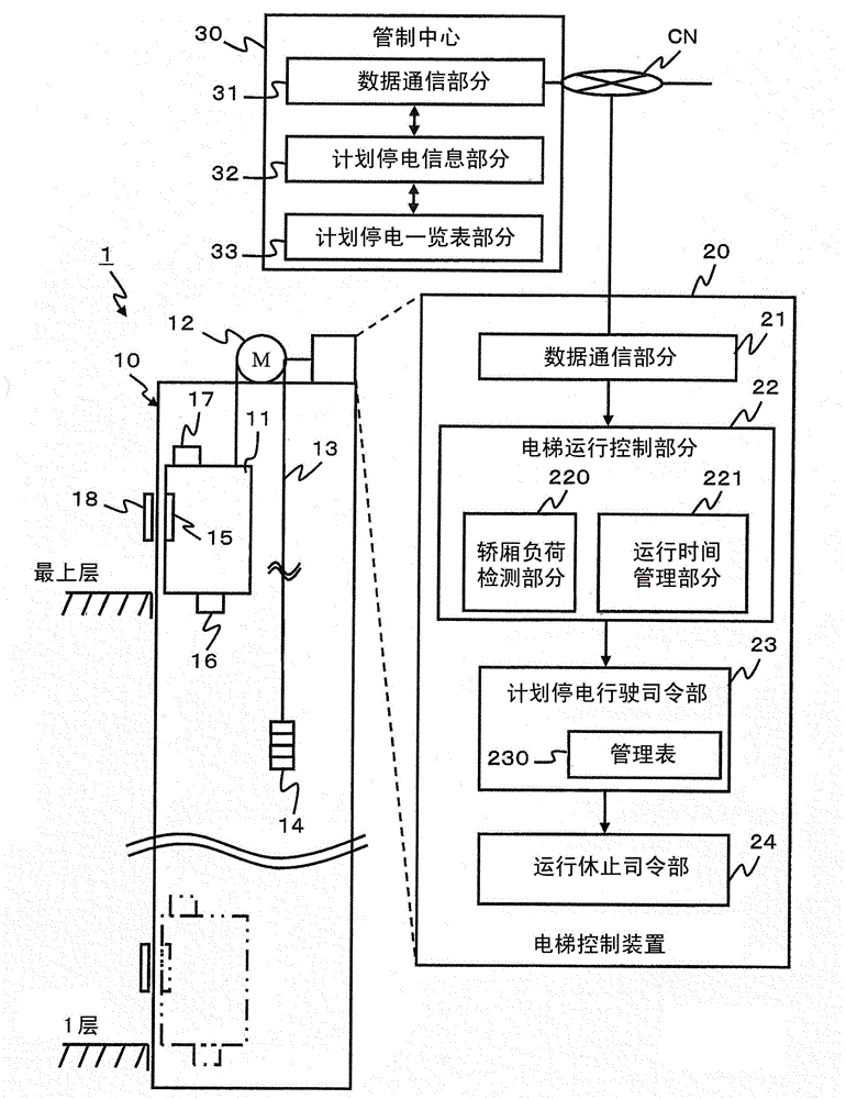
[0018] figure 1 It is an overall configuration diagram of the elevator system 1 according to the first embodiment. The elevator system 1 has, for example, an elevator installation 10 , an elevator control 20 and a control center 30 . For convenience of explanation, one elevator device 10 and one elevator control device 20 are shown in the figure respectively, but actually the control center 30 manages a plurality of elevator control devices 20 .
[0019] Elevator apparatus 10 is installed, for example, in buildings such as office buildings, hotels, apartments, and department stores, and at least one car (elevator car) 11 can move up and down between floors from the first floor to the highest floor.
[0020] The elevator apparatus 10 includes, for example, an elevator car 11 on which passengers ride, a driving device 12 for moving the elevator car 11 up and down by a sling 13 , and a counterweight 14 for balancing the weight of the elevator car 11 . The driving device 12 is c...
no. 2 example
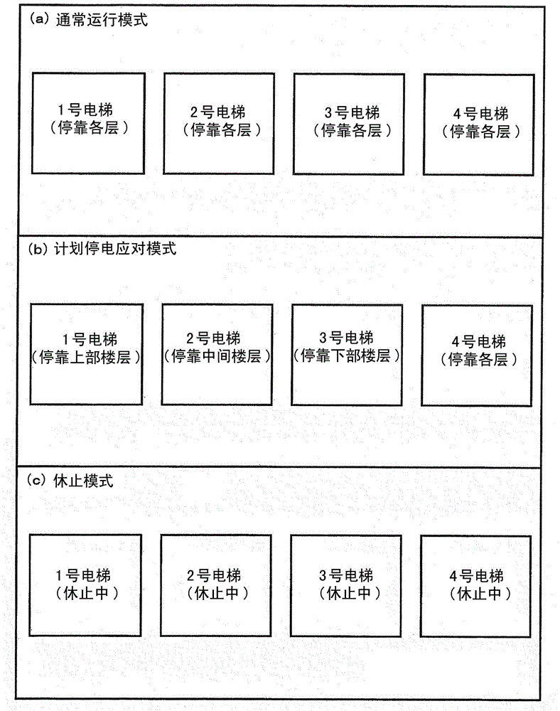
[0050] Refer to the following image 3 A second embodiment will be described. In this embodiment, the case where group management is performed on a plurality of elevator apparatuses will be described as an example.
[0051] Such as image 3 As shown, in the case where there are multiple elevators (for example, No. 1 elevator to No. 4 elevator), the running status of each elevator is set according to the power outage plan. For example, (a) in the normal operation mode, all the elevator apparatuses are operated so that they can stop at each floor. (b) In the planned power outage response mode, the floors that can be stopped by each elevator are set to different floors. For example, Elevator 1 is programmed to reciprocate between the upper and lobby floors, Elevator 2 is programmed to reciprocate between the middle and lobby floors, and Elevator 3 is programmed to reciprocate the lower floors Carry out reciprocating operation between the hall floor and the lobby floor, and se...
no. 3 example
[0054] Refer to the following Figure 4 A third embodiment will be described. In this embodiment, the period during which the planned power failure response mode is executed (planned power failure response time) is set according to the usage status of the elevator apparatus. Figure 4 Indicates the calculation processing of the planned power outage response time. This process may be executed by the control center 30 or may be executed by the control device 20 .
[0055] Hereinafter, a case where processing is executed by the control device 20 will be described as an example. The control device 20 checks the scheduled date and time of the planned power outage with the demand history (S30). The demand history refers to the history data of the operation management of the elevator apparatus 10, and is information indicating how many passengers have taken the elevator apparatus 10 in a certain period of time on a certain day in the past.
[0056] The control device 20 judges wh...
PUM
 Abstract
Description
Claims
Application Information
 - R&D
- Intellectual Property
- Life Sciences
- Materials
- Tech Scout
- Unparalleled Data Quality
- Higher Quality Content
- 60% Fewer Hallucinations
Browse by: Latest US Patents, China's latest patents, Technical Efficacy Thesaurus, Application Domain, Technology Topic, Popular Technical Reports.
© 2025 PatSnap. All rights reserved.Legal|Privacy policy|Modern Slavery Act Transparency Statement|Sitemap|About US| Contact US: help@patsnap.com


