
A multi-antenna array in the form of a curved reflector

A reflector, multi-antenna technology, applied to antennas, antenna unit combinations with different polarization directions, electrical components, etc. Effect

Active Publication Date: 2015-08-19
WUHAN HONGXIN TELECOMM TECH CO LTD
View PDF7 Cites 0 Cited by
  • Summary
  • Abstract
  • Description
  • Claims
  • Application Information

AI Technical Summary

Problems solved by technology

Although the current mobile communication antennas mostly use mutually orthogonal radiating elements to reduce the correlation between co-polarized and differently polarized radiating elements, due to the limitations of the radiating element's own polarization purity, frequency band, bandwidth, beam width, etc. , the cross-polarization discrimination rate is often the difficulty in the development of multi-antenna arrays

Method used


Image

  • A multi-antenna array in the form of a curved reflector
  • A multi-antenna array in the form of a curved reflector
  • A multi-antenna array in the form of a curved reflector

Examples


Embodiment Construction

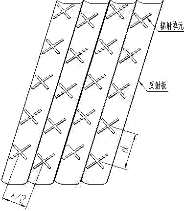
[0018] The multi-antenna array of the present invention includes a reflector, a plurality of antenna radiation units arranged periodically and installed on the reflector, and a feed network arranged on the back of the reflector. The multiple antenna radiating units are electrically connected to each other through the feeding network. The technical solution of the present invention will be described in detail below in conjunction with the drawings and embodiments.

[0019] In order to make the technical problems, technical solutions and beneficial effects to be solved by the invention clearer, the present invention will be further described in detail below in conjunction with the accompanying drawings and embodiments. It should be understood that the specific embodiments described are only used to explain the present invention, not to limit the present invention.

[0020] Such as figure 1 Shown is a schematic diagram of the overall structure of the multi-antenna array.

[0...


PUM


Abstract

The invention provides a curved reflector type multi-antenna array which comprises more than one reflectors, a row of antenna radiation units are mounted on each reflector, and the antenna radiation units are electrically connected with one another through a feed network arranged on the backs of the reflectors; and the multi-antenna array can provide positive or negative 45 degrees of dual-polarization signal coverage. Because the reflectors of the multi-antenna array are wavy, the distances from the feed centers of the radiation units to the reflectors are equal, and consequently, the cross polarization discrimination rate of the multi-antenna array is increased.

Description

technical field [0001] The invention relates to the technical field of mobile communication array antennas, in particular to a multi-antenna array in the form of a bent reflector. Background technique [0002] In the field of wireless mobile communication technology, the antenna as a terminal is mainly used for transmitting and receiving signals. At present, the wireless environment is relatively complex. During the propagation of electromagnetic waves in the wireless channel, due to the reflection, refraction, and loss of the ground surface and obstacles, polarization deflection will occur. For this reason, antennas for mainstream mobile communications are mostly composed of two groups of ±45° dual-polarized radiation units with mutually orthogonal polarization directions. Each group of radiation units satisfies the same array characteristics, so it can effectively deal with the Unfavorable factors such as polarization deflection. At the same time, since the correlation b...

Claims


Application Information

Patent Timeline
Patent Type & Authority Patents(China)
IPC IPC(8): H01Q21/24H01Q15/16
Inventor 郭继权石萌谢晖
Owner WUHAN HONGXIN TELECOMM TECH CO LTD
Learn More