
A circularly polarized phased array antenna element

A phased array antenna and antenna array element technology, which is applied in the direction of antenna arrays, antenna arrays with separate power supply, antennas, etc., can solve the problem of large gain bottom and pattern out-of-roundness, large out-of-roundness, narrow axial ratio bandwidth, etc. problem, to achieve the effect of improving the identification rate

Inactive Publication Date: 2019-01-25
HUBEI SANJIANG SPACE XIANFENG ELECTRONICS&INFORMATION CO LTD
View PDF8 Cites 12 Cited by
  • Summary
  • Abstract
  • Description
  • Claims
  • Application Information

AI Technical Summary

Problems solved by technology

[0004] When the microstrip antenna is used as the element of the circularly polarized phased array antenna, the microstrip antenna has the disadvantages of low power capacity, narrow working bandwidth, narrow axial ratio bandwidth, low gain and large out-of-roundness of the pattern, resulting in unsatisfactory Large roundness and small axial ratio angle cannot meet the system requirements, resulting in a large deviation in the beam pointing accuracy of the phased array antenna, which cannot meet the needs of wide-axis ratio and low out-of-roundness in different applications

Method used


Image

  • A circularly polarized phased array antenna element
  • A circularly polarized phased array antenna element
  • A circularly polarized phased array antenna element

Examples


Embodiment Construction

[0030] In order to make the objectives, technical solutions and advantages of the present invention clearer, the following further describes the present invention in detail with reference to the accompanying drawings and embodiments. It should be understood that the specific embodiments described herein are only used to explain the present invention, but not to limit the present invention.

[0031] In addition, the technical features involved in the various embodiments of the present invention described below can be combined with each other as long as they do not conflict with each other.

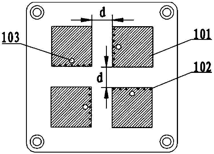
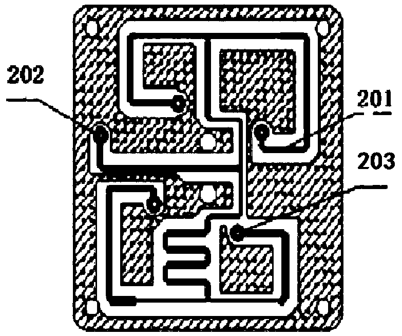
[0032] Figure 1~2 They are the structural schematic diagrams of the circularly polarized phased antenna array element and the circularly polarized phased antenna array element radiation plate in the preferred embodiment of the present invention. Such as figure 1 As shown, the circularly polarized phased array antenna element includes a radiating plate 1, a feeding plate 2, a first feeding cond...


PUM


Abstract

The invention discloses a circularly polarized phased array antenna element. The antenna element comprises a radiation plate, a feeding plate and a first feeding conductor. Four square radiation patches are arranged on the upper part of the radiation plate in turn. Several ground holes and a first feeding hole are arranged on the inner side of the four radiation patches, which are arranged in a straight line and have equal spacing. A 1 / 4 microstrip pow splitter is arrange at that lower part of the feed plate, the second feed hole and four third feed holes corresponding to the first feed hole,the four third feeding holes and the four first feeding holes are electrically connected through the first feeding conductor in turn, the one-quarter microstrip power splitter sequentially shifts thephase of the signal between the second feed hole and the four third feed holes by setting a corresponding metal feed line length, The design of circular polarized phased array antenna element with extremely low out-of-roundness and large axis ratio angle is realized without increasing the size of existing antenna element, which effectively solves the problem of large out-of-roundness and small axis ratio angle of circular polarized phased array antenna, which leads to large deviation of beam pointing accuracy of the whole antenna.

Description

Technical field [0001] The invention belongs to the technical field of antennas, and specifically relates to a circularly polarized phased array antenna element. Background technique [0002] The phased array antenna is a kind of array antenna as the basic structure, combined with the digital phase shifter to realize a large integrated antenna array that can scan the beam at high speed in the entire airspace. It is widely used in modern radars, communications, telemetry and remote sensing, etc. field. Compared with mechanical scanning radar, phased array antenna has fast response speed, convenient beamforming, wide scanning range and high positioning accuracy, and it can track and process multiple targets at the same time. [0003] The existing phased array antenna generally uses a microstrip antenna as an array element, which is small in size, light in weight, and low in cost, and is easy to conform to the surface of the carrier, thereby facilitating the integrated manufacturing ...

Claims


Application Information

Patent Timeline
Patent Type & Authority Applications(China)
IPC IPC(8): H01Q1/38H01Q1/48H01Q1/50H01Q15/24H01Q21/00H01Q21/06
CPCH01Q1/38H01Q1/48H01Q1/50H01Q15/24H01Q21/0006H01Q21/065
Inventor 王鑫晋学羽何琼
Owner HUBEI SANJIANG SPACE XIANFENG ELECTRONICS&INFORMATION CO LTD
Learn More