

Traveling Wave Excitation Antenna And Planar Antenna
- Summary
- Abstract
- Description
- Claims
- Application Information
AI Technical Summary
Benefits of technology
Problems solved by technology
Method used
Image

Examples
first embodiment
100>
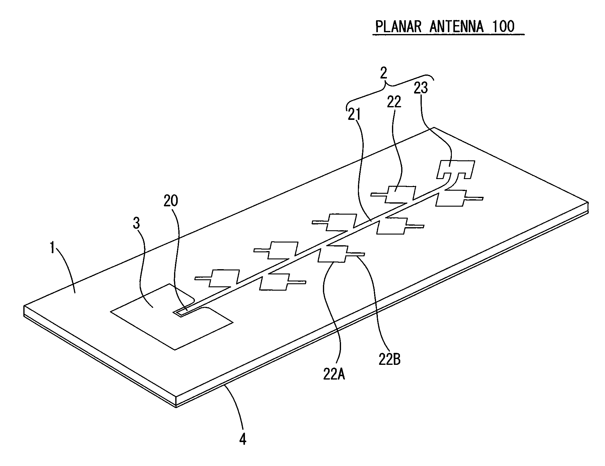
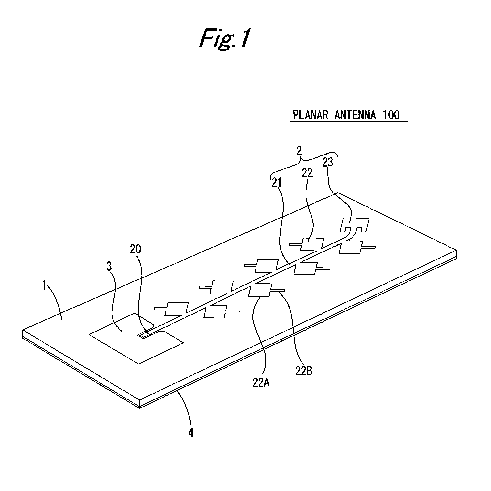
[0041]FIG. 1 is a perspective view illustrating a configuration example of a planar antenna 100 according to a first embodiment of the present invention. The planar antenna 100 is a microstrip antenna in which on both surfaces of a dielectric substrate 1, electrically conductive layers are formed, and by providing a radiating element 22 with an open stub 22B, suppresses radiation of a cross polarized wave by the radiating element 22 to improve cross polarization discrimination.
[0042]The dielectric substrate 1 is a substrate made of fluorine resin containing inorganic fibers, and formed in a tabular and substantially rectangular shape. On the front surface of the dielectric substrate 1, an antenna pattern 2 and converter pattern 3 formed by etching electrically conductive metallic foil are provided. Also, on the back surface of the dielectric substrate 1, a grounding plate 4 that almost covers a whole of the surface and is made of electrically conductive metal is provided, and th...
second embodiment
[0079]In the first embodiment, described are the planar antennas 100 to 102 each of which suppresses the cross polarized wave by using the radiating element 22 having the open stub 22B extending in the cross polarization direction. On the other hand, in the present invention, described is a planar antenna that suppresses a cross polarized wave by using a radiating element 22 having a short stub 22C at one end in a cross polarization direction.
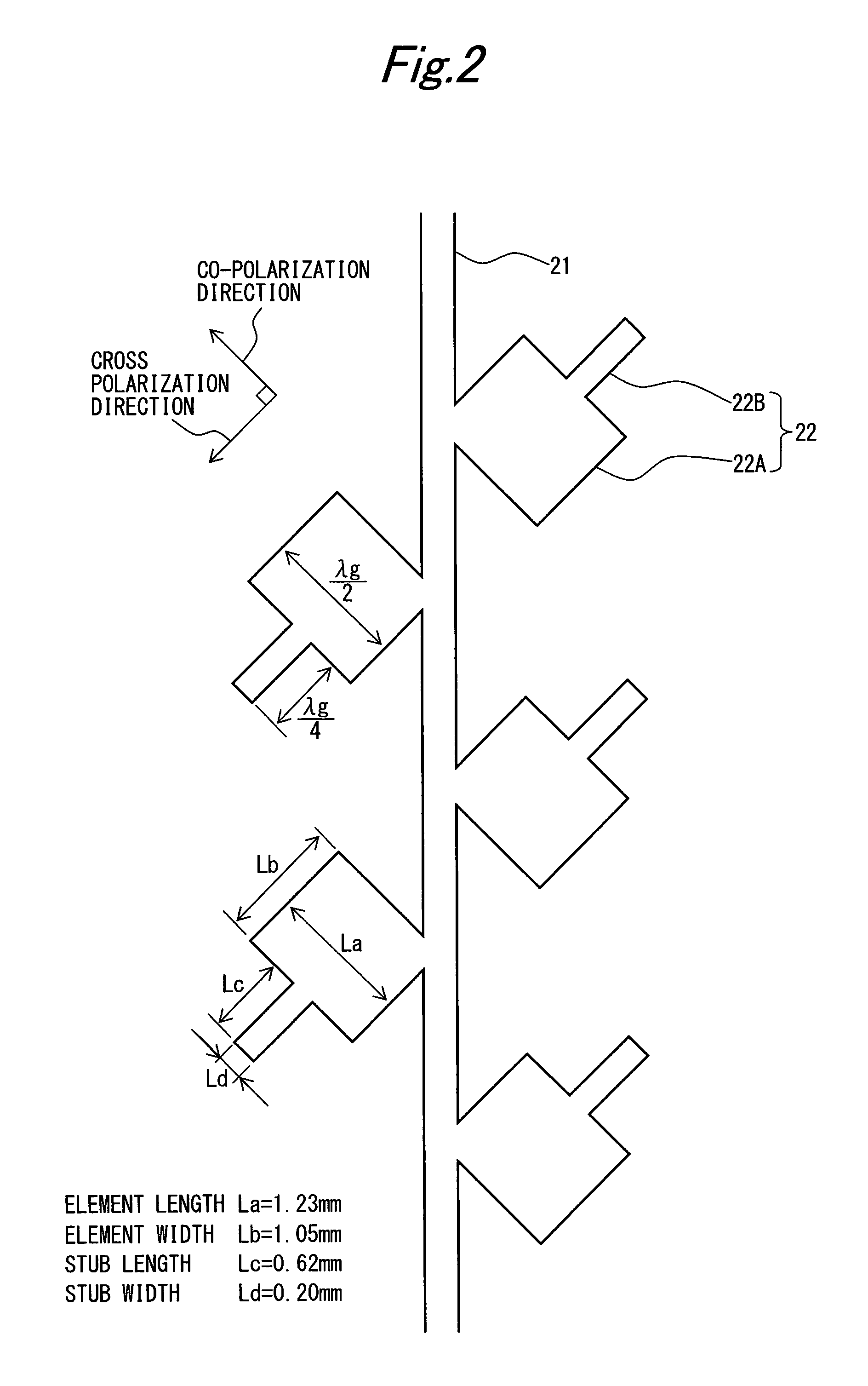
[0080]FIG. 18 is a diagram illustrating a configuration example of the radiating element 22 constituting the planar antenna according to the second embodiment of the present invention. Also, FIG. 19 is a cross-sectional view of the radiating element 22 along a C-C section line in FIG. 18. The radiating element 22 according to the present embodiment is, as compared with the radiating element in FIG. 2, different in that in place of the open stub 22B, the short stub 22C is provided.
[0081]The radiating element 22 is configured to have a substantia...
PUM
 Abstract
Description
Claims
Application Information