An Antenna Array for Improving Cross-polarization Discrimination of Tripole Antennas
A technology of pole antennas and antenna arrays, which is applied in the directions of antenna arrays, antenna arrays, antennas, etc. that are energized separately, can solve the problem of high cross polarization, achieve no waste of space, overcome low cross polarization discrimination, and cross polarization The effect of improved discrimination
- Summary
- Abstract
- Description
- Claims
- Application Information
AI Technical Summary
Problems solved by technology
Method used
Image
Examples
Embodiment 1
[0053] Figure 8 It is the H-plane pattern at 3.3, 3.45 and 3.6GHz of the sub-array placed in rotation and given the appropriate phase to the port. The pattern contains the main polarization and cross polarization ratio curves.
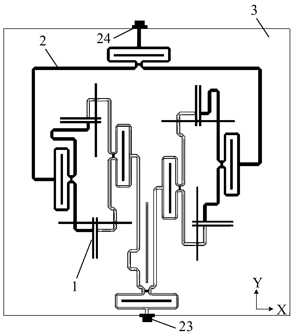
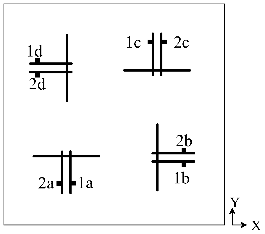
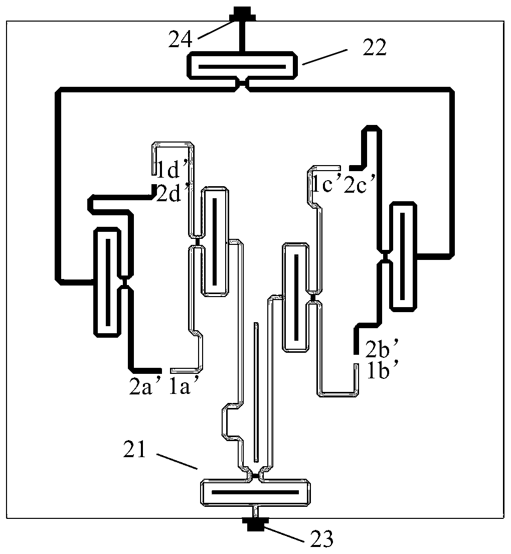
[0054] Such as Figure 10 As shown, the vector current distribution diagrams when the connection points 1a, 1b, 1c, and 1d are excited with the same amplitude, and the feed phases are 180°, 0°, 0°, and 180° respectively. Figure 10 The scale on the left represents the current density distribution, the lighter the color, the larger the current amplitude, on the contrary, the darker the color, the smaller the current amplitude, from Figure 10 It can be seen from the figure that when 1a, 1b, 1c, and 1d are excited with the same amplitude, and the feed phases are 180°, 0°, 0°, and 180° respectively, the energy is coupled to the three poles corresponding to the connection points 1a and 1c respectively One arm 112 of the first half-wave oscillator of the...
Embodiment 2
[0056] Figure 9 It is the H plane pattern at 3.3, 3.45 and 3.6GHz of the sub-array without adopting the array arrangement and feeding mode of the present invention, and the pattern includes the main polarization and cross polarization ratio curves.
[0057] Figure 11 It is a vector current distribution diagram at 3.45 GHz when the tripole antenna unit 1 involved in the present invention is arrayed in a conventional manner (connection points 1a, 1b, 1c, and 1d are excited with equal amplitude and phase). Figure 11 The scale on the left represents the current density distribution, the lighter the color, the larger the current amplitude, and the darker the color, the smaller the current amplitude. From Figure 11 It can be seen from the figure that when the connection points 1a, 1b, 1c, and 1d are excited with the same amplitude and phase, the transmitted energy is coupled to one arm 112 of the first half-wave oscillator and the other arm 132 of the first half-wave oscillato...
PUM
 Abstract
Description
Claims
Application Information
 - R&D
- Intellectual Property
- Life Sciences
- Materials
- Tech Scout
- Unparalleled Data Quality
- Higher Quality Content
- 60% Fewer Hallucinations
Browse by: Latest US Patents, China's latest patents, Technical Efficacy Thesaurus, Application Domain, Technology Topic, Popular Technical Reports.
© 2025 PatSnap. All rights reserved.Legal|Privacy policy|Modern Slavery Act Transparency Statement|Sitemap|About US| Contact US: help@patsnap.com


