
Microgrid reactive power balanced allocation method based on impedance composite control

A technology of impedance compounding and balanced distribution, applied in the field of microgrid, can solve the problems that the accuracy of impedance measurement affects reactive power distribution, harsh impedance matching conditions, and difficulty in satisfying multiple VSIs at the same time

Inactive Publication Date: 2014-11-12
HEFEI UNIV OF TECH
View PDF3 Cites 5 Cited by
  • Summary
  • Abstract
  • Description
  • Claims
  • Application Information

AI Technical Summary

Problems solved by technology

[0011] It can be seen that the above-mentioned impedance matching conditions are very strict, and it is difficult for multiple VSIs to meet the requirements simultaneously.
After adding the virtual impedance, the output impedance of the VSI can be approximately determined by the virtual impedance, so the matching degree of the output impedance can be improved, but the value of the virtual impedance is related to the controller structure, parameters, and sampling delay, resulting in the output of multiple VSIs It is difficult to completely match the impedance; at the same time, the virtual impedance further increases the voltage drop and deteriorates the power quality
In addition, the virtual impedance cannot improve the matching characteristics of the line impedance; in order to compensate the influence of the line impedance on the reactive power distribution, it is necessary to obtain accurate data of the line impedance, which undoubtedly requires the support of the communication connection line, which increases the system cost and the accuracy of the impedance measurement is serious. Influence reactive power distribution

Method used


Image

  • Microgrid reactive power balanced allocation method based on impedance composite control
  • Microgrid reactive power balanced allocation method based on impedance composite control
  • Microgrid reactive power balanced allocation method based on impedance composite control

Examples


Embodiment Construction

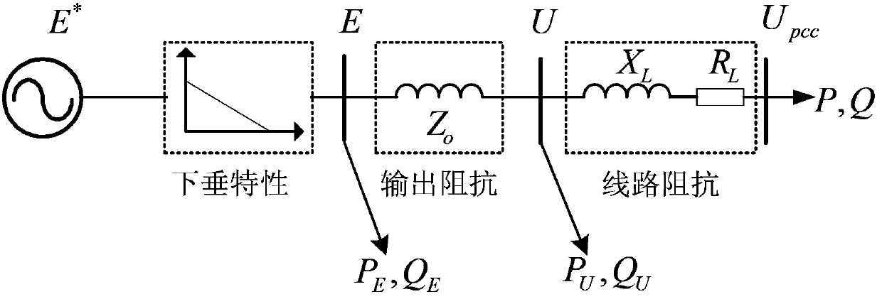
[0047] The technical scheme consists of two parts: a Q-U droop coefficient dynamic adjuster and a Q-U droop control based on virtual impedance compensation. Among them, the Q-U droop coefficient dynamic adjuster dynamically changes the Q-U droop coefficient in real time according to the output active power and reactive power of the VSI; the Q-U droop control based on virtual impedance compensation includes a virtual impedance device, a virtual impedance open-loop compensator and a virtual impedance closed-loop compensator. Part: the virtual impedance adjusts the output impedance of the VSI according to the output current; the virtual impedance open-loop compensator compensates the voltage drop generated by the virtual impedance according to the active and reactive power; the impedance closed-loop compensator uses the PI regulator to control the Q-U droop characteristics.

[0048] The technical scheme of the present invention is, a kind of microgrid reactive power equalization d...


PUM


Abstract

The invention provides a microgrid reactive power balanced allocation method based on impedance composite control. The technical scheme includes that the microgrid reactive power balanced allocation method includes: dynamically changing a droop coefficient in real-time by a dynamic Q-U droop coefficient adjuster according to outputted active power and reactive power of VSI (vertical speed indicator), adjusting VSI output impedance according to output current by Q-U droop control based on virtual impedance compensation, compensating voltage drop generated by virtual impedance by a virtual impedance open-loop compensator according to active power and reactive power, and controlling Q-U droop properties in a closed-loop manner via a PI (power integrations) adjuster by an impedance closed-loop compensator. The microgrid reactive power balanced allocation method has the advantages that voltage drop generated by the virtual impedance is compensated by open loop and closed loop, so that voltage sag generated by virtual impedance is avoided when output impedance is corrected; and mismatching of line impedance is eliminated by adopting a dynamic variable coefficient method and a transient state variable coefficient method, and dynamic and steady averaging properties of reactive power are improved.

Description

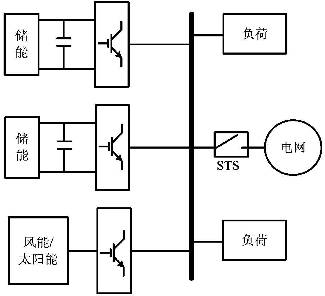
technical field [0001] The invention relates to the technical field of microgrids in electric power systems, in particular to a method for controlling reactive power distribution of microgrids. Background technique [0002] Micro-grid is a new type of intelligent distributed power access method. It is a new type of distributed power system composed of multiple loads, micro-sources, energy storage units and their power electronic interfaces. Its typical topology is as follows: figure 1 shown. exist figure 1 Among them, various forms of micro-sources are connected to the AC bus through AC-DC-AC converters or DC-AC power electronic interfaces. As an intelligent power system, the micro-grid can be connected to the grid or run off-grid. Externally, it appears as a single controlled source, which overcomes the random fluctuations of traditional DG (Distributed Generation, distributed power) and can solve the problem of high penetration rate DG. Grid connection issues, weaken th...

Claims


Application Information

Patent Timeline
Patent Type & Authority Patents(China)
IPC IPC(8): H02J3/18
CPCY02E40/30Y02P80/14
Inventor 杜燕杨向真张健苏建徽茆美琴张国荣
Owner HEFEI UNIV OF TECH
Learn More