Pressure contact type spring pressure test device

A technology of spring pressure and testing device, applied in the direction of measuring device, measuring force, instrument, etc., can solve problems such as interference phenomenon, achieve accurate test results, improve work efficiency, and easy to use.

Inactive Publication Date: 2013-08-14
CHENGDU DAMO PETROLEUM MACHINERY GRP
View PDF5 Cites 30 Cited by
  • Summary
  • Abstract
  • Description
  • Claims
  • Application Information

AI Technical Summary

Problems solved by technology

[0004] The purpose of the present invention is to overcome the problem that existing devices for testing spring pressure have to provide pressure inside the support column, which is prone to interference. A pressure contact

Method used


Image

  • Pressure contact type spring pressure test device

Examples


Embodiment

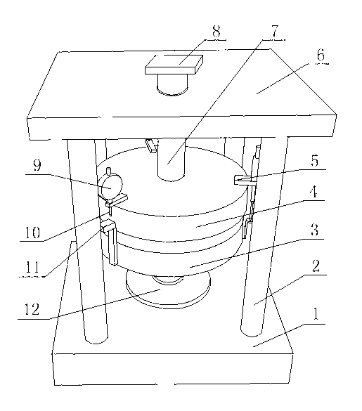
[0020] Such as figure 1 As shown, a spring pressure testing device adopting a pressure contact type includes a base 1, a top plate 6 is arranged on the base 1, a pressure plate is arranged between the top plate 6 and the base 1, one end of the pressure plate is connected with the base 1, and the other end is passed through It passes through the top plate 6 and is arranged outside the top plate 6 , and a contact block 8 is fixed on the end surface. The contact block 8 is a component that is in contact with the pressure structure. The contact block is pressed tightly, and then the pressure plate is driven to press down, and the spring is pressed tightly, and the value is tested.

[0021] Several support columns 2 are arranged between the top plate 6 and the base 1, and the two ends of the support columns 2 are respectively connected with the top plate 6 and the base 1, and the support columns 2 surround the pressure plate. The supporting column 2 and the top plate 6 are positio...


PUM


Abstract

The invention discloses a pressure contact type spring pressure test device which comprises a base; a top plate is arranged on the base; a pressure plate is arranged between the top plate and the base; one end of the pressure plate is connected with the base, and the other end of the pressure plate penetrates the top plate and is arranged at the outer part of the top plate; and a contact block is fixed on the end surface of the pressure plate. The device can solve the interference phenomenon in providing pressure, is simple in structure, and is more convenient to use, the test result is more accurate, and the working efficiency is improved.

Description

technical field [0001] The invention relates to a testing device, in particular to a pressure contact type spring pressure testing device, which belongs to the field of spring pressure testing. Background technique [0002] Most materials have varying degrees of elasticity and, if bent, return to their original shape with considerable force. The great flexibility of the branches of saplings and young trees must have been noticed very early in human history, as many primitive cultures took advantage of this property by wedging a stick behind a specially made door or cage, or by using a slipknot. Pulls down on a rod; the rod or rod springs back once the tension is released. They use this method to catch birds and animals. In fact, the bow uses the elastic spring of the sapling in this way; first draw the bow back, then let it go and let it rebound. During the Middle Ages, this idea began to appear on machinery, such as weaving machines, lathes, drilling rigs, flour mills an...

Claims


Application Information

Patent Timeline
IPC IPC(8): G01L1/00
Inventor 项勇严元齐
Owner CHENGDU DAMO PETROLEUM MACHINERY GRP
Why Eureka
Try Eureka