Rotary LED fluorescent lamp cap

A kind of LED fluorescent lamp and rotating technology, which is applied in the direction of light source, point light source, semiconductor device of light-emitting element, etc. It can solve the problems of fixed irradiation direction, inability to adjust, and inability to adjust the direction of LED fluorescent tube, and achieve the effect of expanding the lighting range

Active Publication Date: 2014-12-10
CHONGQING SILIAN OPTOELECTRONICS SCI & TECH
View PDF4 Cites 3 Cited by
  • Summary
  • Abstract
  • Description
  • Claims
  • Application Information

AI Technical Summary

Problems solved by technology

Compared with traditional fluorescent lamps that emit light at 360°, LED fluorescent lamps have a narrower luminous angle of only 120°. After the LED fluorescent lamp tube is installed on the existing lamp holder, the LED fluorescent lamp tube and the lamp holder are fixed, and the direction of the LED fluorescent lamp tube cannot be adjusted. Therefore, the LED fluorescent lamp The irradiation direction of the fluorescent tube is fixed and cannot be adjusted, satisfying various installation methods

Method used


Image

  • Rotary LED fluorescent lamp cap
  • Rotary LED fluorescent lamp cap
  • Rotary LED fluorescent lamp cap

Examples


Embodiment Construction

[0019] Below in conjunction with accompanying drawing and embodiment the present invention will be further described:

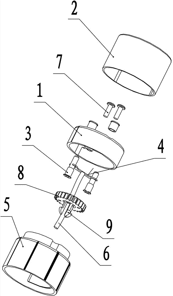
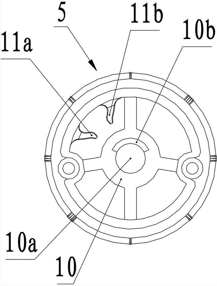
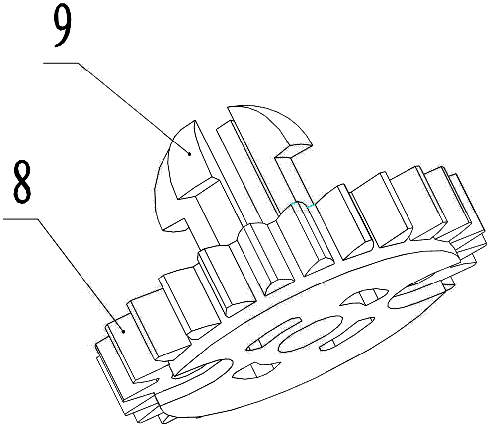
[0020] see Figure 1 to Figure 6 A rotary LED fluorescent lamp cap includes an end cap 1, a plug cap 2, an electrode 3, a wiring short piece 4 and a cylindrical base 5. The electrode 3 is installed on the outer surface of the end cover 1, the electrode 3 is connected to the power line 6 through the wiring short piece 4, the electrode 3 and the wiring short piece 4 are fixed to the end cover 1 by punching, and the plug cap 2 is Cylindrical, the plug cap 2 is sleeved and fixed on the end cap 1, the electrode 3 is located in the plug cap 2, and the plug cap 2 plays the role of protecting the electrode 3. The inner surface of the end cover 1 is fixed with a gear 8 made of plastic through a screw 7, one end surface of the gear 8 is in contact with the inner surface of the end cover 1, and the middle part of the other end surface of the gear 8 is vertically provi...


PUM


Abstract

The invention provides a rotary LED fluorescent lamp cap which comprises an end cover and a cylindrical base. Electrodes are arranged on the outer surface of the end cover and are connected with a power line. The rotary LED fluorescent lamp cap is characterized in that a gear is fixed to the inner surface of the end cover, one end surface of the gear is in contact with the inner surface of the end cover, an elastic retaining pin is perpendicularly arranged in the middle of the other end surface of the gear, a mounting support is fixed into the base, a mounting hole is arranged in the middle of the mounting support, elastic limiting lugs are arranged on the inner wall of the base, the gear is arranged in the base, the elastic retaining pin on the gear is rotatably clamped in the mounting hole on the mounting support, and the elastic limiting lugs are abutted onto teeth of the gear. The rotary LED fluorescent lamp cap has the advantages that the orientation of an LED fluorescent lamp tube can be adjusted by the rotary LED fluorescent lamp cap, and the illumination range of the LED fluorescent lamp tube is expanded.

Description

technical field [0001] The invention relates to a lamp holder of an LED fluorescent lamp, in particular to a lamp holder of a rotating LED fluorescent lamp. Background technique [0002] With the continuous promotion of LED green energy-saving lighting, the demand for LED lamps is also increasing. Among them, LED fluorescent lamps are favored by commercial lighting and civil lighting. Compared with traditional fluorescent lamps that emit light at 360°, LED fluorescent lamps have a narrower luminous angle of only 120°. After the LED fluorescent lamp tube is installed on the existing lamp holder, the LED fluorescent lamp tube and the lamp holder are fixed, and the direction of the LED fluorescent lamp tube cannot be adjusted. Therefore, the LED fluorescent lamp The irradiation direction of the fluorescent tube is fixed and cannot be adjusted, satisfying various installation methods. Contents of the invention [0003] The technical problem to be solved by the present invent...

Claims


Application Information

Patent Timeline
Patent Type & Authority Patents(China)
IPC IPC(8): F21V21/002F21Y101/02F21Y115/10
Inventor 胡栋晏艮川黎朝进
Owner CHONGQING SILIAN OPTOELECTRONICS SCI & TECH
Why Eureka
Try Eureka