
Position and posture measurement method of high-speed rolling body

A technology of pose measurement and rolling body, which is applied in the directions of measuring device, measuring angle, photogrammetry/video surveying, etc., can solve the problems of difficult matching of rolling body marking points and high speed

Active Publication Date: 2013-08-21
DALIAN UNIV OF TECH
View PDF9 Cites 28 Cited by
  • Summary
  • Abstract
  • Description
  • Claims
  • Application Information

AI Technical Summary

Problems solved by technology

[0005] The technical problem to be solved in the present invention is to overcome the defects of the prior art, and to invent a vision-based high-speed rolling body pose measurement method to solve the measurement problems caused by the high speed of the measured object and its own rolling. The binocular vision method for measuring the pose of a rolling body moving at high speed extends the traditional method for measuring the pose of a non-rolling body to a method for measuring the pose of a rolling body, improves the accuracy of the measurement, and solves the problem of pose measurement. During the process, the marking point blanking problem caused by the rolling of the measured object solves the problem of difficult matching of the rolling body marking points.

Method used

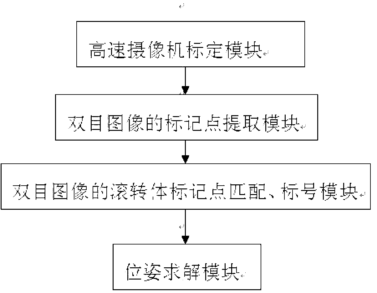
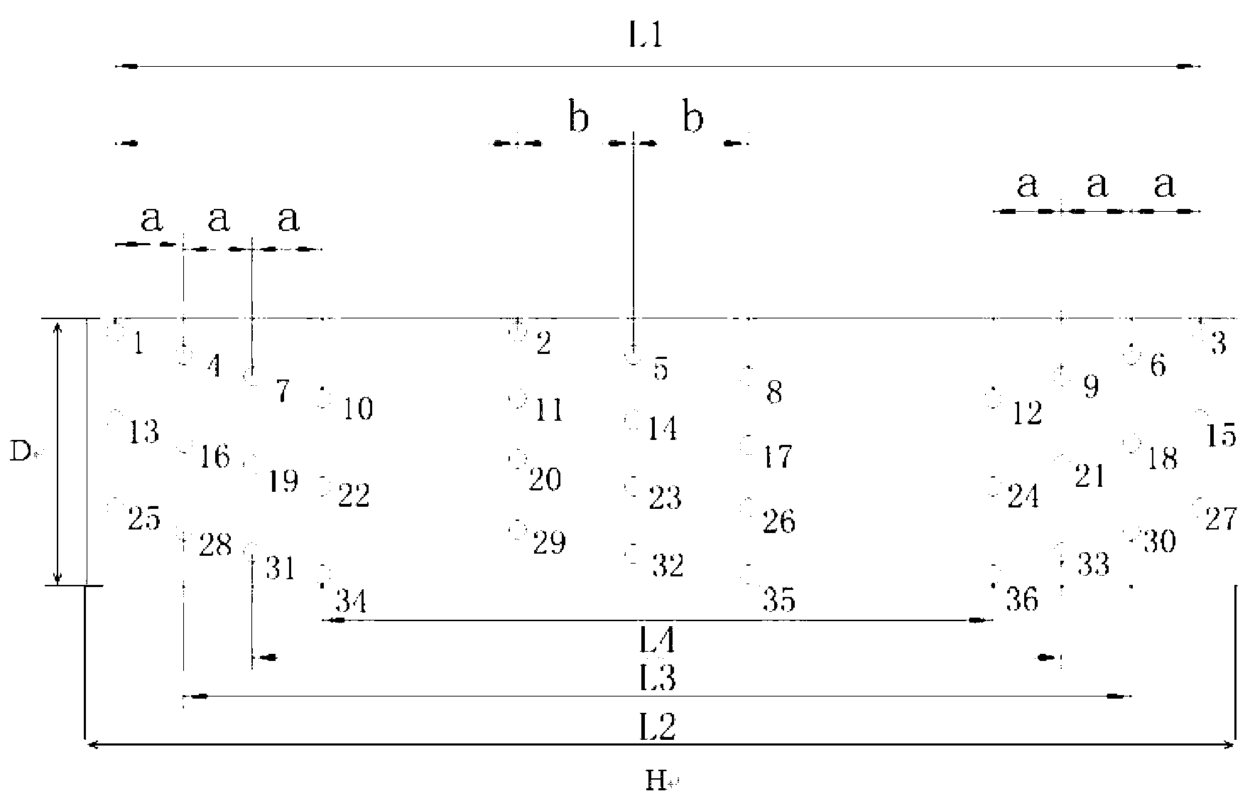

Image

  • Position and posture measurement method of high-speed rolling body
  • Position and posture measurement method of high-speed rolling body
  • Position and posture measurement method of high-speed rolling body

Examples


Embodiment Construction

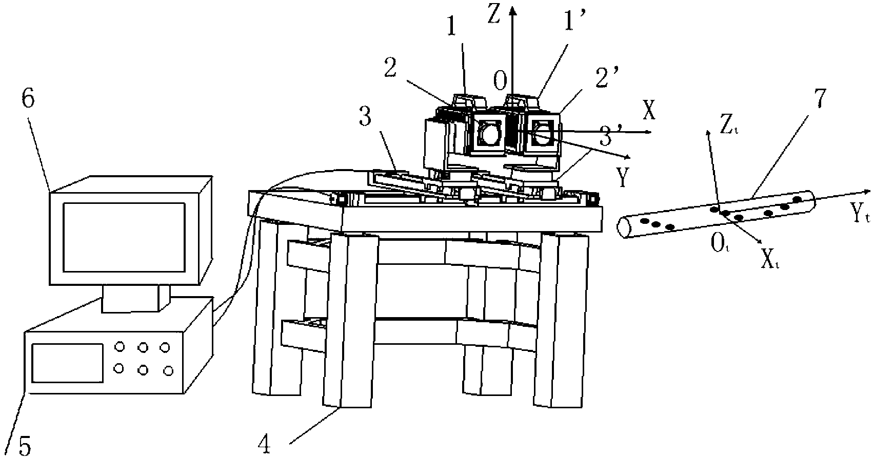
[0052] The specific embodiments of the present invention will be described in detail below in conjunction with the technical solutions and accompanying drawings. attached figure 1 It is a model diagram of the vision-based high-speed rolling body pose measurement device. This device collects the position information of the marked points on the surface of the rolling body 7 to be measured by two left and right high-speed cameras 1, 1', establishes a local coordinate system, and finds the rotation and translation relationship between the local coordinate system and the world coordinate system, which is The pose information of the rolling body to be measured.

[0053] The installation method of the device is as follows: the air flotation anti-vibration table 4 is placed on the ground, and the M6 ​​threaded hole array on the surface of the air flotation anti-vibration table 4 is connected to the communication holes on the left and right two four-dimensional orthogonal electronical...


PUM


Abstract

The invention discloses a position and posture measurement method of a high-speed rolling body, belongs to the technical field of computer visual measurement, and relates to a precise measurement method of space positions and postures of the high-speed rolling body based on vision. According to the measurement method, a binocular vision system is adopted, motion images of the measured rolling body can be collected in real time by means of a left high-speed camera and a right high-speed camera, and picture information transmitted by the left high-speed camera and the right high-speed camera is processed by an image work station. 36 mark points with known positions are evenly machined on the surface of the measured rolling body in the mode of special mark points, and accordingly the problem that the mark points on the surface of the measured rolling body disappear in the motion process is solved. Three collinear mark points are machined each time the measured rolling body rotates by 30 degrees around the axis of the rolling body in a mark point special layout mode. In the mark point special layout mode, the problem that the mark points disappear due to rolling of a target article is solved, and the position and posture measurement of the high-speed rolling body can be effectively completed.

Description

technical field [0001] The invention belongs to the technical field of computer vision measurement and relates to a vision-based precise measurement method for the spatial position and attitude of a high-speed rolling body. Background technique [0002] Object pose measurement technology has a very wide range of applications in various fields such as aviation, aerospace, military industry, and navigation. The object pose information refers to the general term of the position and attitude information of the target object. The position information refers to the translation amount of the target object relative to the reference coordinate system; and the attitude information refers to the rotation amount of the target object relative to the reference coordinate system. In the field of aviation, aerospace and national defense, the measured target has the characteristics of high-speed movement in a large field of view, and most of the measured targets will roll around themselves ...

Claims


Application Information

Patent Timeline
IPC IPC(8): G01B11/03G01B11/26G01C1/00G01C11/00
Inventor 刘巍贾振元鲁文博马鑫崔晓春张洋尚志亮
Owner DALIAN UNIV OF TECH
Learn More