Respiration-rate dependent respiratory assistance

A technology of breathing rate and breathing assistance, which is applied in the direction of respirators, drug devices, and other medical devices, and can solve problems such as discomfort of subjects

Active Publication Date: 2013-08-21
KONINKLIJKE PHILIPS ELECTRONICS NV
View PDF3 Cites 8 Cited by
  • Summary
  • Abstract
  • Description
  • Claims
  • Application Information

AI Technical Summary

Problems solved by technology

The subject may experience discomfort when the breathing device begins to inhale or exhale out of sync with the subject's natural breathing rhythm

Method used


Image

  • Respiration-rate dependent respiratory assistance
  • Respiration-rate dependent respiratory assistance
  • Respiration-rate dependent respiratory assistance

Examples


Embodiment Construction

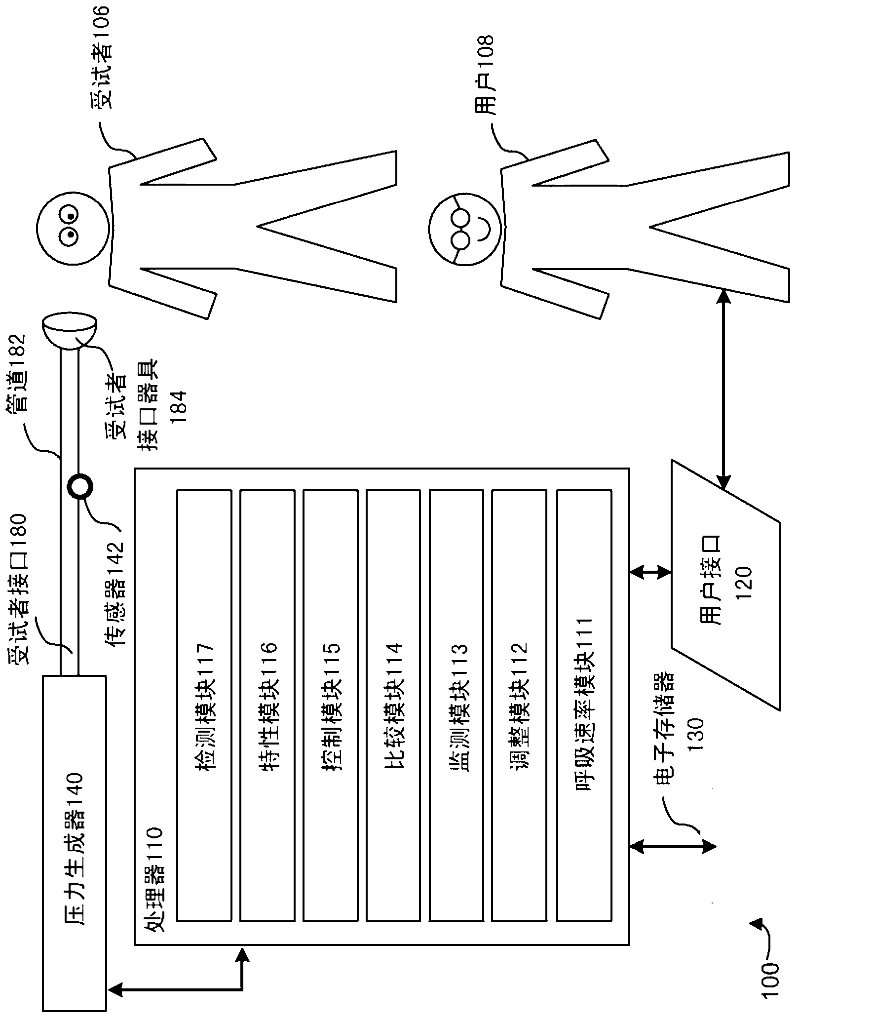
[0010] figure 1 A system 100 configured to control breathing assistance of a subject, a subject 106 and a user 108 are shown. Specifically, system 100 provides breathing assistance to subject 106 such that cumulative tidal volume during inspiration and / or expiration can be monitored and used to control the acceleration of breathable gas delivered to the airway of the subject. Pressure level of pressurized flow. This may provide more comfortable breathing assistance for subject 106 than conventional systems. In one embodiment, system 100 includes processor 110, user interface 120, electronic storage 130, pressure generator 140, subject interface 180, one or more sensors 142, and / or other components.

[0011] Pressure generator 140 may be configured to provide a pressurized flow of breathable gas for delivery to the airway of a subject. Pressure generator 140 may be configured such that one or more gas parameters of the pressurized flow of breathable gas are controlled in acc...


PUM


Abstract

Respiratory assistance is provided to a subject in the form of a pressurized flow of breathable gas. The pressure of the gas is eased during expiration and increased during inspiration. Changes in pressure are triggered and / or cycled based on the monitoring of tidal volume. Volume thresholds that cause triggering and / or cycling are adjusted based on an observed or measured breath rate.

Description

technical field [0001] The present invention relates to machine-assisted breathing of a patient. Background technique [0002] Machine-assisted respiration of a patient or subject is known in the art. Common examples may include positive airway pressure devices such as continuous or bilevel positive airway pressure (CPAP / BiPAP) and / or other devices. Respiratory devices may assist subjects in inhaling, exhaling, or both. The subject may experience discomfort when the breathing device begins to inhale or exhale out of sync with the subject's natural breathing rhythm. Improved comfort may assist in improving therapeutic limitations regarding the use of respiratory equipment. Contents of the invention [0003] The present disclosure relates to a method for controlling respiratory assistance of a subject having an airway. In one embodiment, the method comprises: generating a pressurized flow of breathable gas for delivery to the airway of a subject at an inspiratory pressur...

Claims


Application Information

Patent Timeline
Patent Type & Authority Applications(China)
IPC IPC(8): A61M16/00
CPCA61M2016/0027A61M2016/003A61M2016/0036A61M2016/0039A61M2205/50A61M2230/42A61M16/024A61M16/00
Inventor S·M·西贝纳勒尔L·A·巴洛维尔其恩M·劳拉拉普安特
Owner KONINKLIJKE PHILIPS ELECTRONICS NV
Why Eureka
Try Eureka