Bidirectional parting continuous forging system of forming die of pipe end upsetting device

A technology for forming molds and pipe end thickening, which is applied in metal processing equipment, manufacturing tools, forging/pressing/hammer devices, etc., can solve the problems of inability to achieve continuous forging, prolong working time, and low working efficiency, and save time. , Improve work efficiency and save energy

Active Publication Date: 2015-03-25
NANTONG PUMENGSHENG MACHINERY MFG
View PDF9 Cites 0 Cited by
  • Summary
  • Abstract
  • Description
  • Claims
  • Application Information

AI Technical Summary

Problems solved by technology

It cannot achieve continuous forging, and needs to be heated again after the first thickening, which prolongs the working time, reduces work efficiency and wastes energy

Method used


Image

  • Bidirectional parting continuous forging system of forming die of pipe end upsetting device

Examples


Embodiment Construction

[0015] The present invention will be described in further detail below in conjunction with the accompanying drawings and specific embodiments.

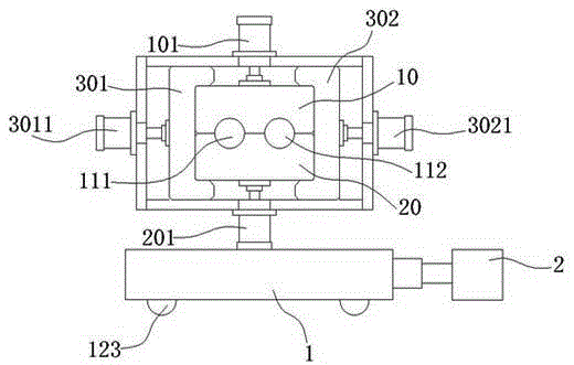
[0016] figure 1 It schematically shows a two-way parting continuous forging system for forming dies of pipe end thickening equipment according to an embodiment of the present invention.

[0017] Such as figure 1 As shown, the pipe end thickening equipment forming die bidirectional parting continuous forging system of the present invention includes: an upper module 10 and a lower module 20, the upper module 10 and the lower module 20 are rectangular blocks, and the upper module 10 and the lower module 20 are interlocked together to form a molding die.

[0018] Wherein, the lower surface of the upper module 10 is provided with at least two semicircular first cavity grooves in parallel along its axis; the upper surface of the lower module 20 is provided with at least two semicircular second cavity grooves in parallel along its axis; T...


PUM


Abstract

The invention discloses a bidirectional parting continuous forging system of a forming die of a pipe end upsetting device. The bidirectional parting continuous forging system of the forming die of the pipe end upsetting device comprises an upper die block and a lower die block, and the upper die block and the lower die block are both rectangular die blocks and are arranged in a mutual snap fit mode to form the forming die; the forming die is provided with at least two forming cavities which are arranged in parallel; a first die opening hydraulic cylinder is arranged above the upper die block and a second die opening hydraulic cylinder is arranged under the lower die block; the upper die block and the lower die block are locked through locking devices; and the forming die is arranged on the upper surface of a movable platform, and the movable platform is connected with a pushing cylinder. The bidirectional parting continuous forging system of the forming die of the pipe end upsetting device saves the upsetting time, improves the working efficiency and meanwhile saving energy sources.

Description

technical field [0001] The invention relates to the field of pipe end thickening equipment, in particular to a two-way parting continuous forging system for forming dies of the pipe end thickening equipment for realizing continuous forging. Background technique [0002] The pipe end is thickened, that is, the inner and outer diameter of the pipe end changes, and the reason is that the mold increases the wall thickness. [0003] The principle of pipe end thickening is that after the pipe end is thickened, it is sent into the thickening mold cavity of the thickening machine, the mold frame is clamped by the mold opening cylinder, and the mandrel is penetrated into the inner wall of the pipe end to pier thickening. In order to achieve the purpose of pipe end thickening. [0004] At present, in the prior art, the mold frame of its thickening equipment only includes one molding cavity, and it is a one-way parting of the upper module. The pipe end thickening process is as follow...

Claims


Application Information

Patent Timeline
Patent Type & Authority Patents(China)
IPC IPC(8): B21J13/02B21J5/06
Inventor 肖天甫
Owner NANTONG PUMENGSHENG MACHINERY MFG
Why Eureka
Try Eureka