Non- pneumatic tire

A tire and tread technology, applied to non-pneumatic tires, tire parts, vehicle parts, etc., can solve problems such as different tires and difficult tire production

Active Publication Date: 2013-09-04
MICHELIN & CO CIE GEN DES ESTAB MICHELIN
View PDF5 Cites 8 Cited by
  • Summary
  • Abstract
  • Description
  • Claims
  • Application Information

AI Technical Summary

Problems solved by technology

[0005] However, such a tire is difficult to produce because the material of the rubb

Method used


Image

  • Non- pneumatic tire
  • Non- pneumatic tire
  • Non- pneumatic tire

Examples


Embodiment Construction

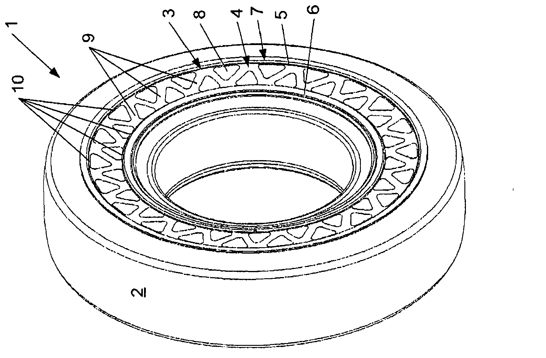
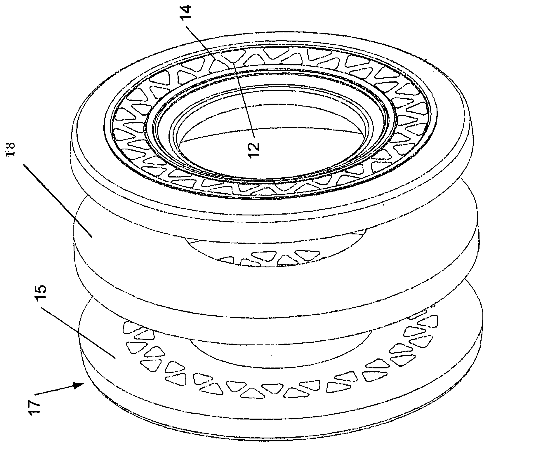
[0058] Figure 1a A tire 1 is shown comprising a rubber tread portion 2 extending in the circumferential direction of the tire 1 for contacting the ground. The tread portion 2 is preferably provided with a tread pattern having protrusions 13, such as Figure 5 shown. The specific design of the tread portion 2 is however not critical to the invention and can also be determined by a person skilled in the art. The tread pattern may, for example, be specifically configured for running in wet and / or dry conditions, etc., or may be specifically configured for the specific ground on which it will be used.

[0059] The tire 1 may be configured to be mounted on any known type of vehicle, such as for example but not limited to cars, trucks, and the like.

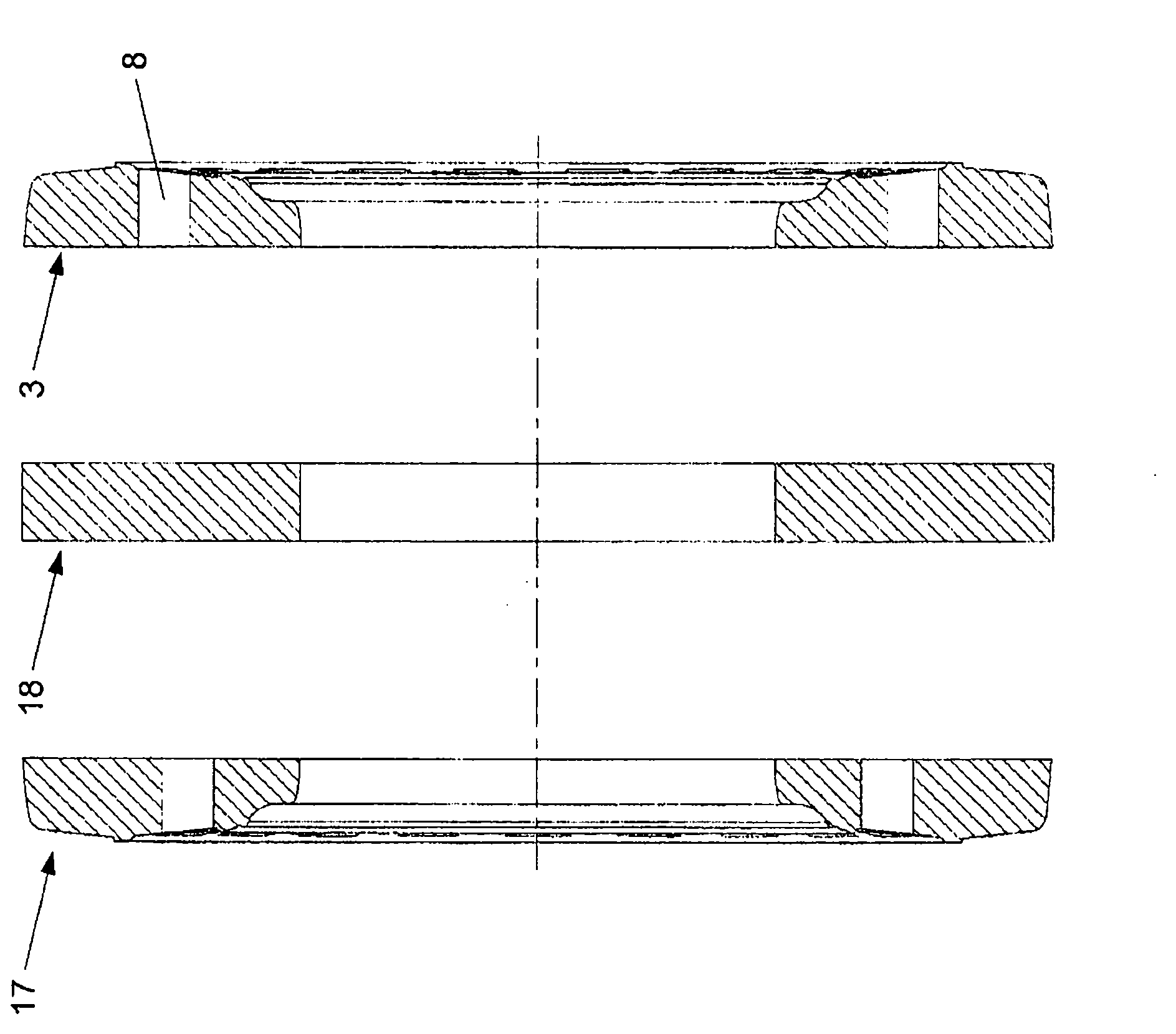
[0060] The tire 1 also includes a frame ring 3 . The carcass ring 3 contacts the tread portion 2 and extends therealong so as to support the vehicle on the tread portion 2 . The frame ring 3 is produced from frame parts 4 . The f...


PUM


Abstract

A tire (1) comprises a rubber tread portion (2) and a truss ring (3), wherein the rubber tread portion (2) extends in circumferential direction of the tire (1) and is provided for contacting a ground surface, and the truss ring (3) contacts and extends along the tread portion (2) for supporting the vehicle on the tread portion (2), and is composed of truss members (4) which form two circumferential chords (5, 6) concentrically positioned with respect to the tread portion (2) and a truss web (7) interconnecting the chords (5, 6). The truss members (4) are made of a truss member material comprising rubber and having an E modulus of between 4 - 18 MPa.

Description

technical field [0001] The invention relates to a tire according to the preamble of the first claim. Background technique [0002] It is known that the safety of a vehicle (either while driving or during a stop) can be improved by avoiding the following situation: the pneumatic tires of such vehicles, due to, for example, leakage of the pneumatic tire (this leakage makes the pneumatic tire air suddenly leaves the tire), which suddenly loses its supporting properties. It is also known to inflate a pneumatic tire with liquid polyurethane instead of air. After curing of the polyurethane inside the tire, the tire provides good support properties to the vehicle while driving and during stops, respectively called dynamic and static properties in the context of the present application. Furthermore, when the tire is punctured, a sudden loss of the tire's bearing properties is avoided, since the polyurethane is cured and cannot leave the tire through the tear. However, the liquid ...

Claims


Application Information

Patent Timeline
IPC IPC(8): B60C7/10
CPCB60C7/107B60C7/102
Inventor H·范德维尔莱
Owner MICHELIN & CO CIE GEN DES ESTAB MICHELIN
Why Eureka
Try Eureka