Bearing device for rotating shaft

A bearing device, a technology for a rotating shaft, applied in the direction of a bearing, a shaft, a bearing, a bearing, etc., which rotate in motion, can solve the problems of poor workability, increased component cost, and increased material cost, and achieve the effect of suppressing shape deformation and realizing component cost.

Active Publication Date: 2015-07-22
TAKANO CO LTD
View PDF5 Cites 0 Cited by
  • Summary
  • Abstract
  • Description
  • Claims
  • Application Information

AI Technical Summary

Problems solved by technology

Therefore, there are various disadvantages associated with the use of metal materials. Specifically, there are various disadvantages such as the following: there is a limit to the overall weight reduction; the workability at the time of manufacture is poor; and the material cost increases due to the blank.
[0008] Second, since separate bearings are installed at the front and rear of the casing, and the rotating shaft is supported by the bearings in a freely rotatable structure, two bearings are required as other components in addition to the casing, and cause Increase in man-hours for assembling the bearing unit
As a result, the increase in the cost of parts due to the increase in the number of parts and the increase in the manufacturing cost due to the increase in the number of assembly man-hours have become important causes of cost increases that cannot be ignored.

Method used


Image

  • Bearing device for rotating shaft
  • Bearing device for rotating shaft
  • Bearing device for rotating shaft

Examples


Embodiment Construction

[0036] Next, preferred embodiments of the present invention will be listed and described in detail with reference to the drawings.

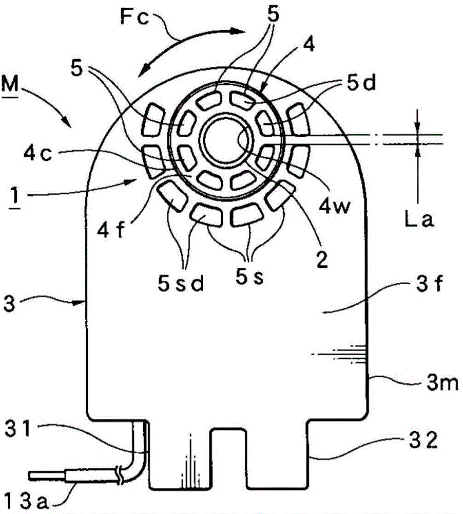
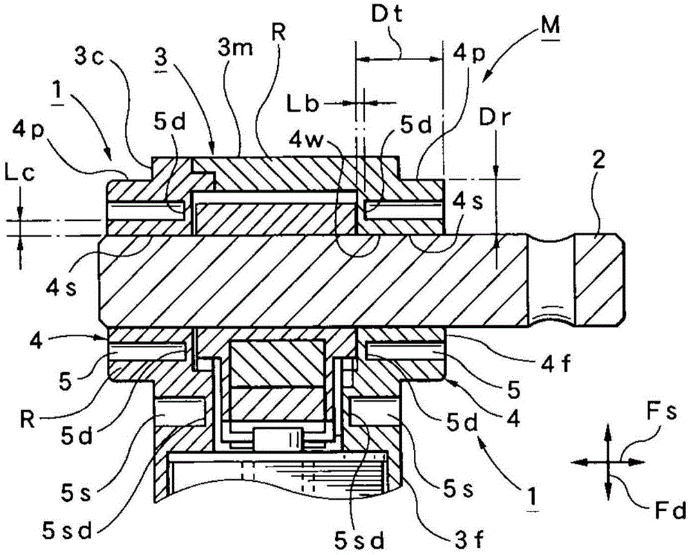
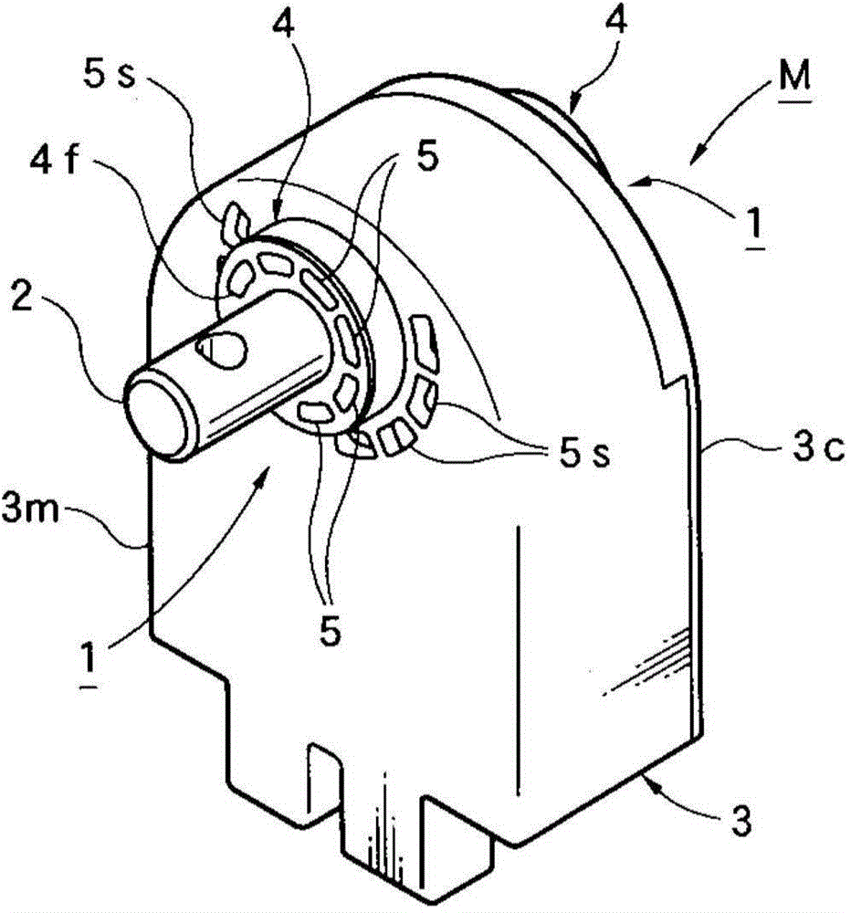
[0037] First, refer to Figure 1 to Figure 7 The structure of the rotary solenoid M provided with the bearing device 1 of this embodiment is demonstrated.

[0038] The rotary solenoid M is provided with a housing 3 forming an outer contour, such as Figure 5 As shown, the case 3 is composed of a case main body 3m and a case cover 3c that closes the opening of the case main body 3m. The case main body portion 3m and the case cover portion 3c are each integrally molded from a synthetic resin material R excellent in moldability and light weight. In this case, the type of synthetic resin material R is not limited to a specific type, but a material with excellent dimensional stability and thermal stability (heat resistance), for example, PBT (polybutylene terephthalate) is preferred. ester) resin materials, etc. in addition, figure 1 Reference nu...


PUM


Abstract

The invention provides a bearing device for a rotating shaft. Shape deformations during manufacturing (molding) and using are inhabited at a minimized extent, fully stability and reliability as a bearing are ensured, cost reduction of parts and cost reduction manufacturing are achieved, mechanical strength is ensured, and effects of lightweight, manufacturing ease improvement and material cost reduction are obtained. A bearing part is disposed on a housing and supports the rotating shaft to be capable of rotating freely. When the bearing device provided with the bearing part is formed, the bearing part is integrally formed by utilizing a synthetic resin material and the housing in such a manner that the bearing part forms in the shape of a ring which has a specific thickness in the axial direction and a specific annular thickness in the radial direction, and a plurality of tolerance absorption recessed parts are formed in an end face of the bearing part; and the multiple tolerance absorption recessed parts are configured in such a manner that the tolerance absorption recessed parts are spaced at specific intervals in the circumferential direction, and the bottom is selected as a specific thickness, so the distance between the tolerance absorption recessed parts and the inner circumferential face of the bearing part is selected as the specific thickness.

Description

technical field [0001] The present invention relates to a bearing device for a rotary shaft that rotatably supports the rotary shaft by being provided in a housing such as a rotary solenoid. Background technique [0002] Conventionally, as a bearing device provided in a housing to rotatably support a rotating shaft, a bearing device provided in a rotary solenoid disclosed in Patent Document 1 is known. [0003] The rotary solenoid disclosed in this document 1 is composed of the following parts: a shaft portion (rotation shaft) which is rotatably supported by a casing; and a movable portion whose one end is fixed to the shaft portion and the other end is free. end, and the movable part has a magnet; and a pair of electromagnetic coil parts, which are fixed to the casing and arranged on both sides of the movable part at a predetermined interval, and the pair of electromagnetic coil parts have a Electricity control is used to selectively attract the iron core of the movable pa...

Claims


Application Information

Patent Timeline
IPC IPC(8): H02K33/16H01F7/14
CPCF16C17/02F16C32/04F16C33/20F16C35/00F16C39/06
Inventor 仓田操北村将志
Owner TAKANO CO LTD
Why Eureka
Try Eureka