

Air-conditioning control system
A technology of air conditioners and air conditioners, which is applied in the directions of air conditioning systems, heating and ventilation control systems, and control inputs related to air characteristics. It can solve problems such as the decrease in the comfort of indoor personnel, and achieve energy saving and energy consumption.
- Summary
- Abstract
- Description
- Claims
- Application Information
AI Technical Summary
Problems solved by technology
Method used
Image

Examples
no. 1 approach 》
[0023]
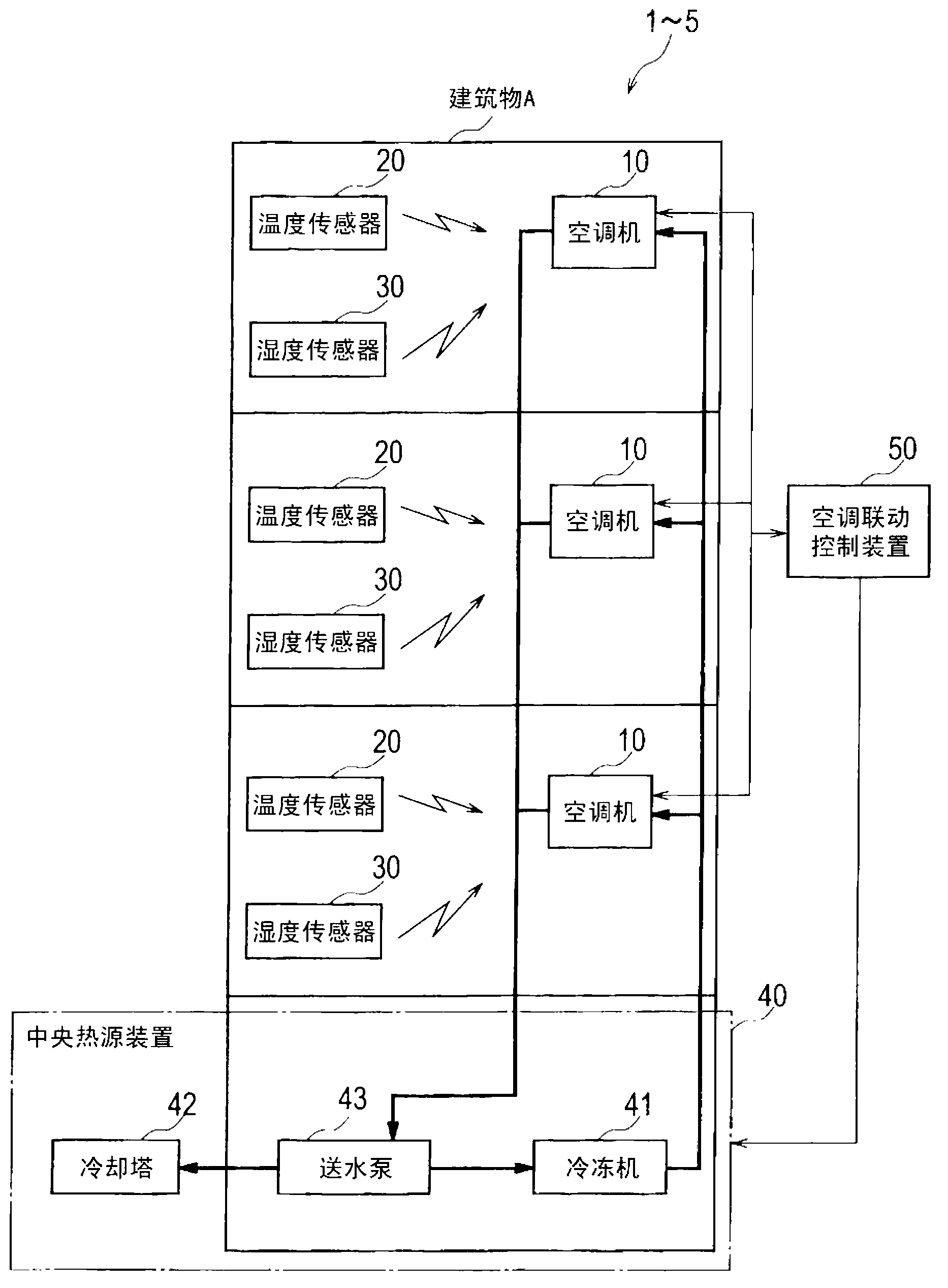
[0024] exist figure 1 A general view of the air-conditioning control system 1 according to the first embodiment of the present invention is shown in .
[0025] However, in the case of a large building, since the room is large, the room is divided into a plurality of control areas, and a plurality of air conditioners are installed in a machine room near the room corresponding to each control area. In this case, hereinafter, each control area is also referred to as a room for brevity.
[0026] The air-conditioning control system 1 is used to control air-conditioning in a building A to be air-conditioned. This air conditioning control system 1 includes: an air conditioner 10 installed in each room in the building A; a temperature sensor 20 installed in each room in order to measure the room temperature and send the measured value to each air conditioner 10 ; and a humidity sensor 30 , which is installed in each room in order to measure the indoor humidity and send th...
no. 2 approach 》
[0070] (Structure of the air-conditioning control system of the second embodiment)
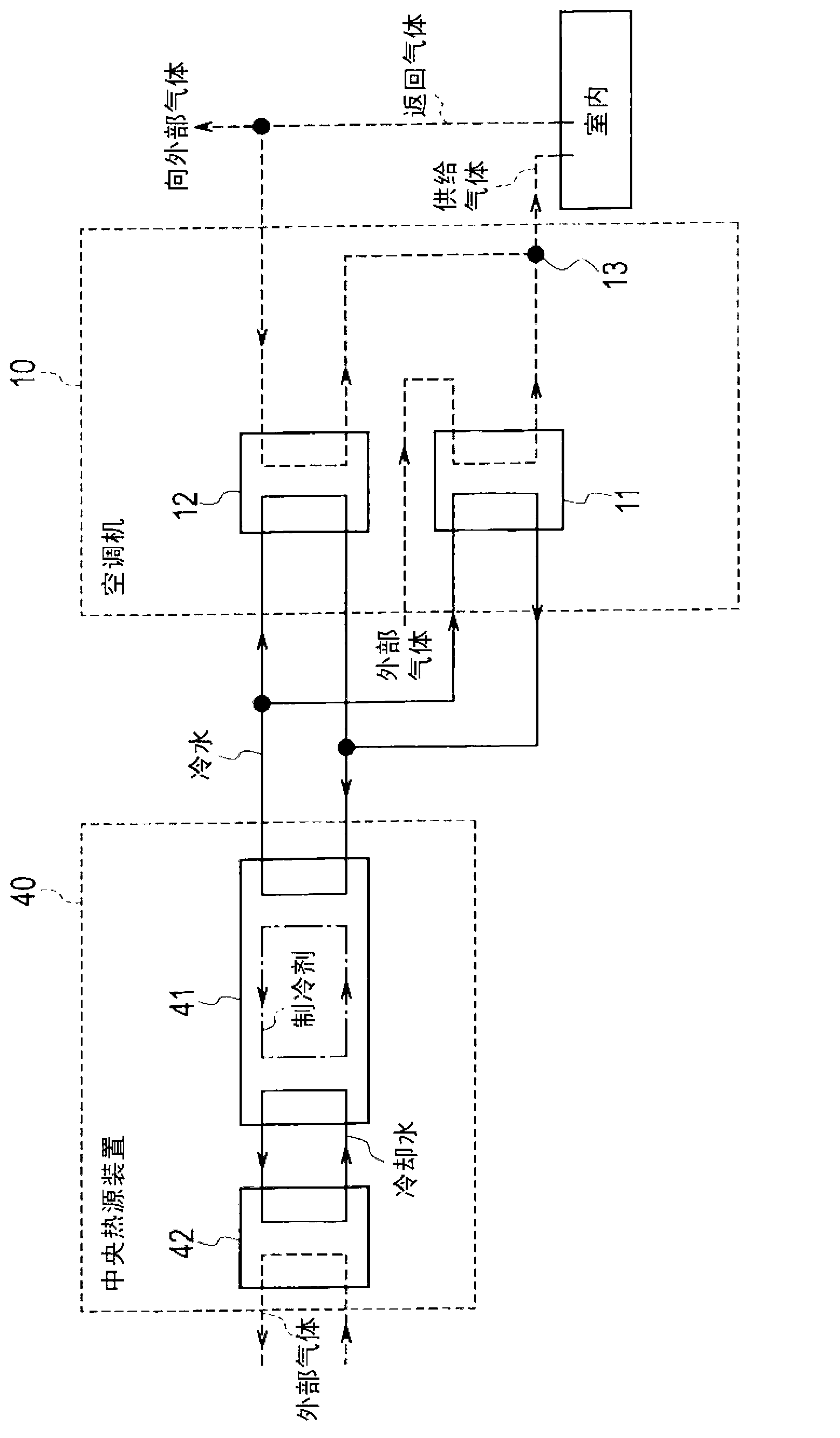
[0071] The structure and figure 1 as well as figure 2 The structure of the first embodiment shown is the same. Therefore, a detailed description of the configuration of the second embodiment is omitted.
[0072] (Operation of the air-conditioning control system of the second embodiment)
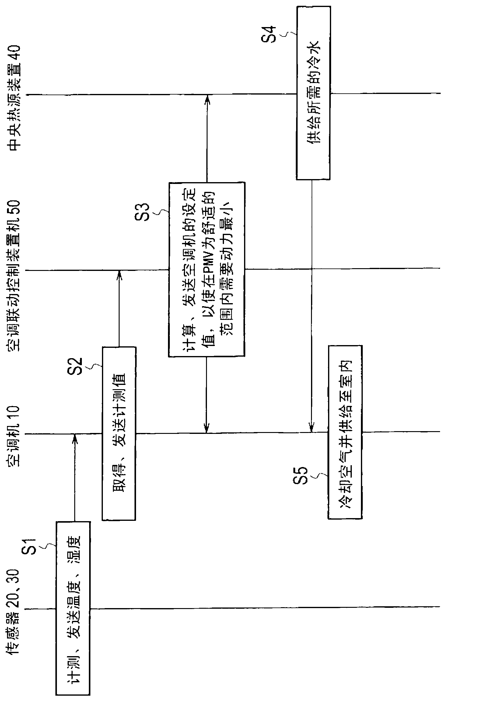
[0073] The operation of the air-conditioning control system 2 in the second embodiment except image 3 Except for the calculation of the set value of each air conditioner 10 in step S3, it is the same as the first embodiment. Therefore, detailed description of the same parts as those of the first embodiment will be omitted.
[0074] For the second embodiment image 3 In Step S3, the air-conditioning interlocking control device 50 calculates the set value of each air conditioner 10 so as to minimize the required energy consumption within the PMV within the comfortable range.
[0075] exist Figure 4 I...
no. 3 approach 》
[0083] (Structure of the air-conditioning control system of the third embodiment)
[0084] The air-conditioning control system 3 according to the third embodiment of the present invention is configured such that at least one of a carbon dioxide sensor (not shown) or a human body sensor (not shown) is installed in a room to be air-conditioned. other structures with figure 1 as well as figure 2 The first embodiment shown is the same. Therefore, detailed description of the same parts as those of the first embodiment will be omitted.
[0085] The carbon dioxide sensor measures the indoor carbon dioxide concentration discharged from the occupants, and sends it to the air conditioner 10 . In addition, the human detection sensor detects the number of people in the room of the air-conditioning control target, and transmits the number to the air conditioner 10 .
[0086] (Operation of the air-conditioning control system of the third embodiment)
[0087] For the operation of the a...
PUM
 Abstract
Description
Claims
Application Information