Air-conditioner wind deflecting mechanism and air conditioner

A technology of air guide mechanism and air conditioner indoor unit, which is applied in the direction of airflow control element, etc., can solve the problems of single fixed air supply or swing air supply mode, complex air guide structure of air conditioner, and inability to choose air supply, etc., to meet individual needs , Simple structure, comfortable air supply

Active Publication Date: 2013-09-11
GD MIDEA AIR-CONDITIONING EQUIP CO LTD +1
View PDF5 Cites 10 Cited by
  • Summary
  • Abstract
  • Description
  • Claims
  • Application Information

AI Technical Summary

Problems solved by technology

Since the movement structure and movement mode of the air guide plate and the air guide louver 2' are fixed, only a single fixed air supply or swing air supply mode can be realized, and the air supply range can only be between a single range and a maximum range. Choose between different ranges of air supply, which cannot be selected according to the actual needs of users
[0003] see image 3 and Figures 4a-4c , different from the above scheme, in order to solve the above problems, in the prior art, some air conditioner manufacturers set up two air outlets of the air conditioner indoor unit, and use two motors 4' to control and drive the air guide louvers 2 in the two air outlets respectively 'Realize the selection of different air supply combinations to achieve the change of the air supply range. The air guide structure of this air conditioner is very complicated and the cost is high

Method used


Image

  • Air-conditioner wind deflecting mechanism and air conditioner
  • Air-conditioner wind deflecting mechanism and air conditioner
  • Air-conditioner wind deflecting mechanism and air conditioner

Examples


Embodiment 1

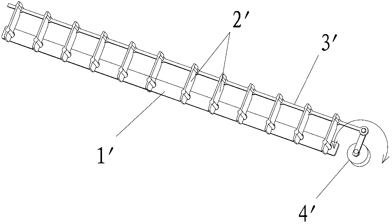
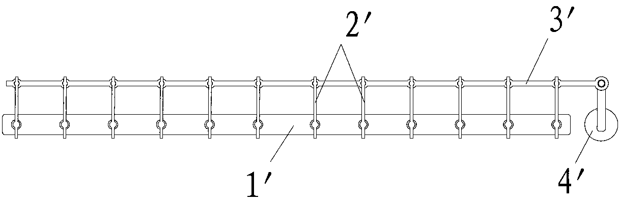
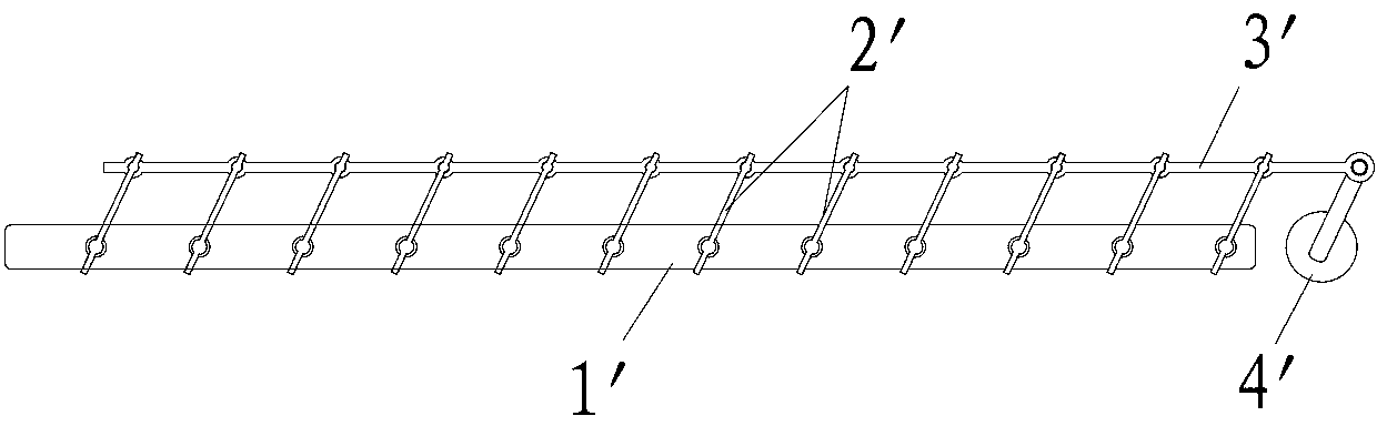
[0034] see Figure 5 Embodiment 1 of the present invention provides an air-conditioning air guiding mechanism including a base 1, an air outlet assembly 2 and a driving part 3, and the air outlet assembly 2 includes a first connecting rod 211, a second connecting rod 212 and a And a plurality of air guide louvers 22 on the second connecting rod 212, the flexible connection of the first end of the first connecting rod 211 and the first end of the second connecting rod 212 is hinged, specifically, can be in the first The first end of the connecting rod 211 is provided with a connecting hole 2111, and the first end of the second connecting rod 212 is provided with a connecting shaft 2121, and the connecting hole 2111 is set on the connecting shaft 2121 to realize the hinge; as an alternative, also Conversely, the connecting shaft 2121 is arranged on the first connecting rod 211, and the connecting hole 2111 is arranged on the second connecting rod 212; and the second end of the f...

Embodiment 2

[0040] The difference between the present embodiment and the first embodiment lies in the structure of the slider and the connection method between the slider and the connecting rod. refer to Figure 9 In this embodiment, the slider 41" includes a slider 412" and a protruding shaft 411", the slider 412" is spherical, and the slider 41" can be integrally formed with the second end of the first connecting rod 211, or can be Detachable connection. And protruding shaft 411 " and sliding body 412 " are preferably integrally formed, but also can be connected together after forming separately, and the structure of connecting sliding hole 11 is the same as in embodiment one. In this example, sliding block 41 The spherical sliding body of "can slide in the connecting sliding hole 11 very flexibly, and is not easily interfered. Other structures are the same as those in Embodiment 1, and will not be repeated here.

Embodiment 3

[0042] The structure of this embodiment is not shown, please refer to Figure 5 It should be understood that the difference between the third embodiment and the first embodiment is that: the second end of the first connecting rod 211 is hinged to the base 1, specifically a connecting column (not shown) can be provided on the base 1, and the first The second end of the connecting rod 211 is provided with a connecting hole 2110, and the connecting hole 2110 is sleeved on the connecting column to realize hinge connection, so that the first connecting rod 211 can rotate around the connecting column and its second end as a whole; The first end of the connecting rod 211 is provided with a guide sliding hole (not shown) with a certain length, and the first end of the second connecting rod 212 is provided with a sliding column (not shown) adapted to the guiding sliding hole. The sliding column can slide along the length direction of the sliding hole in the sliding hole, so as to reali...


PUM


Abstract

The invention provides an air-conditioner wind deflecting mechanism and an air conditioner. The wind deflecting mechanism comprises a substrate, a wind outlet assembly and a driving component, wherein the wind outlet assembly comprises a first connecting rod, a second connecting rod and a plurality of wind deflecting shutters, the wind defector shutters are arranged on the first connecting rod and the second connecting rod, a first end portion of the first connecting rod is movably connected with a first end portion of the second connecting rod, a second end portion of the first connecting rod is in movable linkage with the substrate, the driving component is in rigid connection with a second end portion of the second connecting rod so as to drive the second connecting rod and the first connecting rod to rotate and change the wind deflecting angle of the wind deflecting shutters, and the wind deflecting mechanism is adopted on an indoor unit of the air conditioner. The air-conditioner wind deflecting mechanism is simple in structure and low in cost. The purposes that wind is supplied dispersedly in a large range and wind is supplied intensively in a small range can be achieved by the fact that only one motor drives the wind deflecting shutters. The wind deflecting mechanism is applied to the indoor unit of the air conditioner, the wind supplying range is selected according to requirements of a user, and personalized needs of consumers are met. In addition, due to the fact that the wind deflecting shutters form a continuous and even wind supplying area spatially, the wind supplying makes people feel more comfortable.

Description

technical field [0001] The invention belongs to the technical field of air conditioner manufacturing, and more specifically relates to an air guide mechanism for an air conditioner and an air conditioner using the air guide mechanism. Background technique [0002] see figure 1 and Figure 2a-2c , the existing household air conditioner indoor unit realizes the air supply in different directions and different areas, through the upper and lower air deflectors' swinging up and down and the motor 4' driving the left and right air deflecting louvers 2 set on the base 1' through the connecting rod 3' 'Achieved by swinging left and right. Since the movement structure and movement mode of the air guide plate and the air guide louver 2' are fixed, only a single fixed air supply or swing air supply mode can be realized, and the air supply range can only be between a single range and a maximum range. It is not possible to select different ranges of air supply according to the actual ...

Claims


Application Information

Patent Timeline
IPC IPC(8): F24F13/14
Inventor 华龙吕艳红
Owner GD MIDEA AIR-CONDITIONING EQUIP CO LTD
Why Eureka
Try Eureka