Touch sensitive user interface

A user, 3D technology, applied in the input/output of user/computer interaction, using reradiation, instrumentation, etc.

Active Publication Date: 2013-09-11
MICROSOFT TECH LICENSING LLC
View PDF12 Cites 23 Cited by
  • Summary
  • Abstract
  • Description
  • Claims
  • Application Information

AI Technical Summary

Problems solved by technology

The touch interface

Method used


Image

  • Touch sensitive user interface
  • Touch sensitive user interface
  • Touch sensitive user interface

Examples


Embodiment Construction

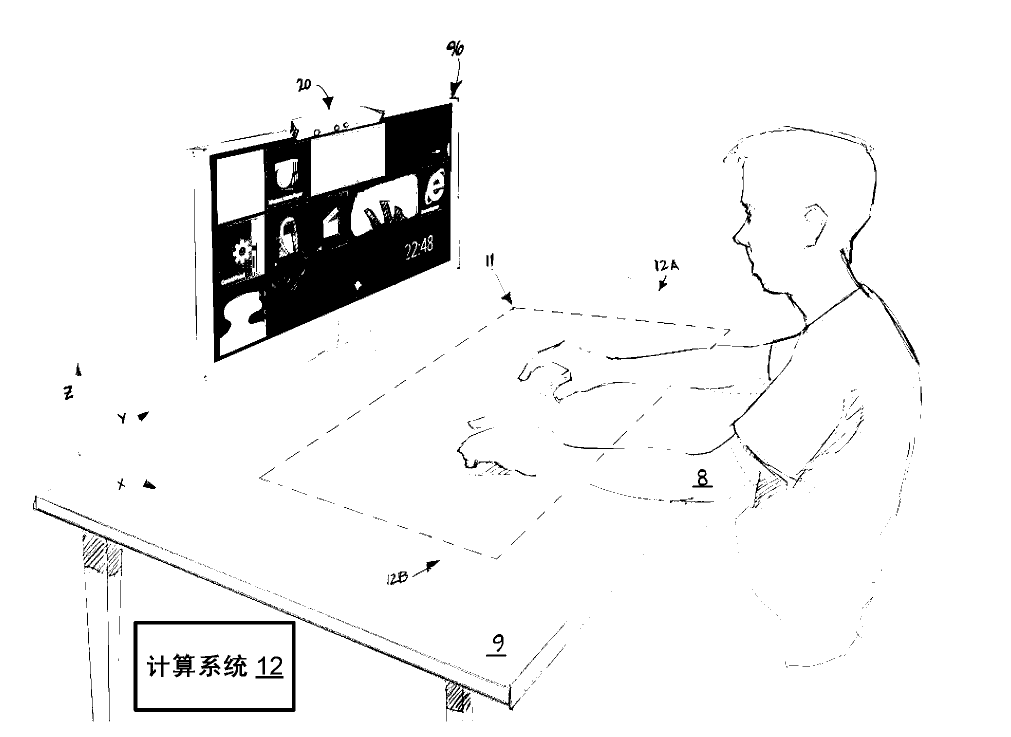
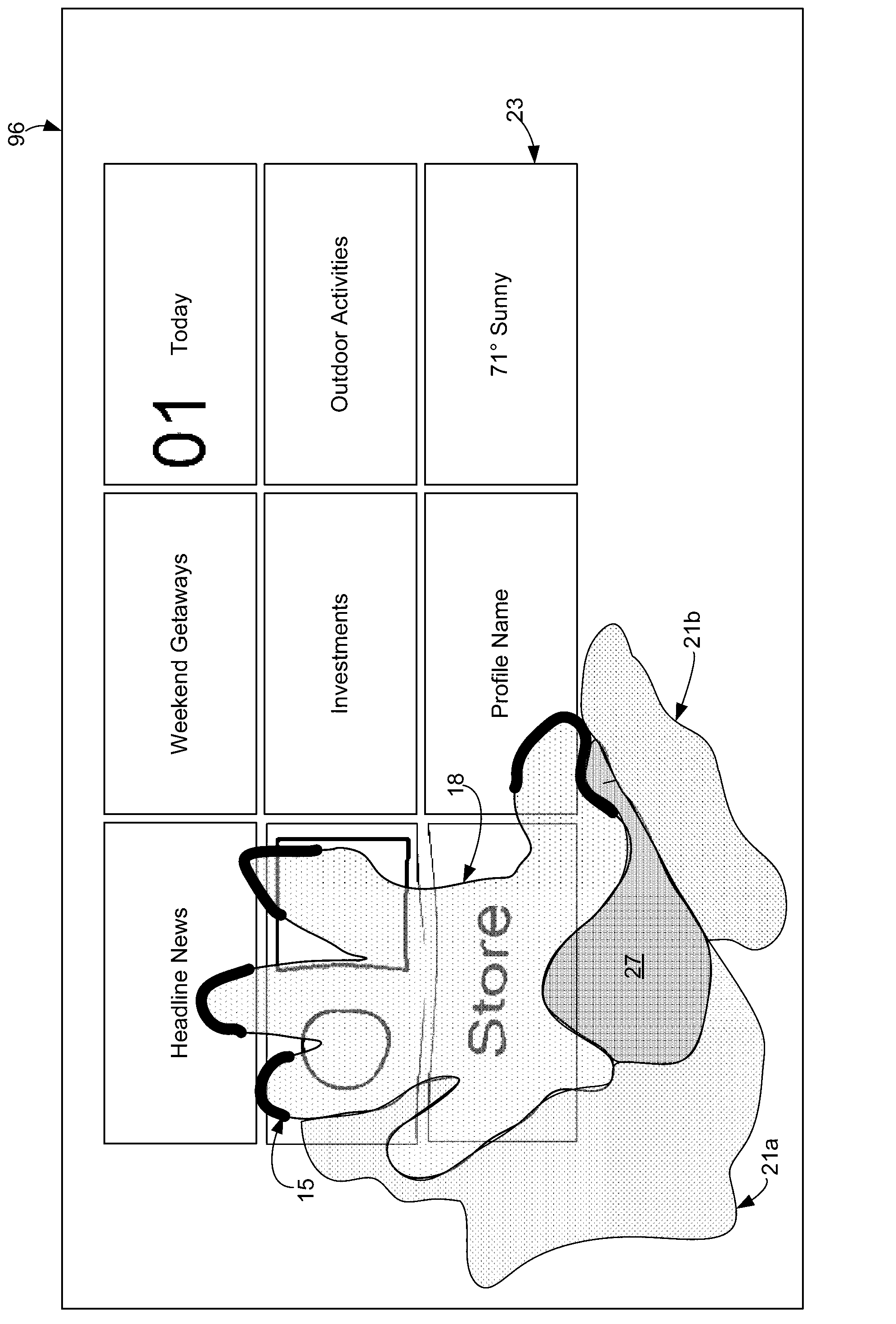
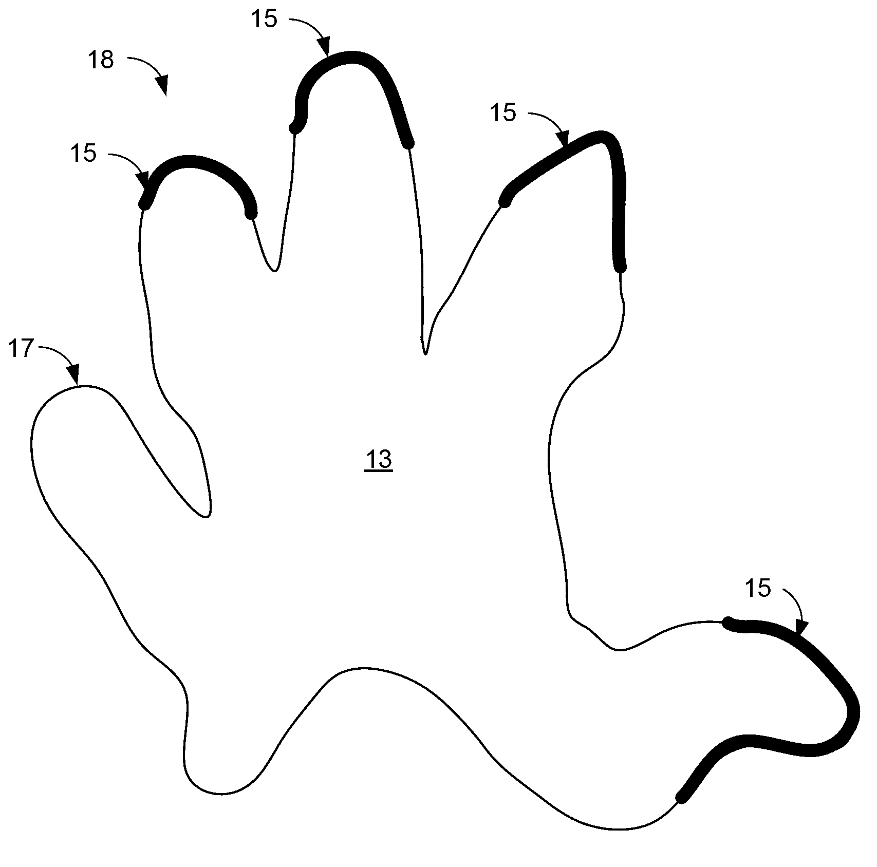
[0038] Embodiments of the present technology will now be described, which generally relate to touch interfaces for electronic devices. A touch interface can include any surface. As one example, a countertop can be used as a touch-sensitive interface. In one embodiment, the system determines the touch area of ​​the surface and correlates the touch area with the display of the electronic device to which the input is provided. The system may have a 3D camera that identifies the relative position of the user's hand to the touch area to allow user input. Note that the user's hand does not obscure the display. The system can present a representation of the user's hand on the display to enable the user to interact with elements on the display.

[0039] A wide variety of user input functions are possible, including but not limited to the following. A user may touch a surface (or touch area) to select elements on the display. Users can move their fingers across the surface to drag...


PUM


Abstract

A system and a method are disclosed for providing a touch interface for electronic devices. The touch interface can be any surface. As one example, a table top can be used as a touch sensitive interface. In one embodiment, the system determines a touch region of the surface, and correlates that touch region to a display of an electronic device for which input is provided. The system may have a 3D camera that identifies the relative position of a user's hands to the touch region to allow for user input. Note that the user's hands do not occlude the display. The system may render a representation of the user's hand on the display in order for the user to interact with elements on the display screen.

Description

technical field [0001] The present invention relates to touch-sensitive user interfaces. Background technique [0002] In the past, computing devices used keyboards and mice as input devices. These input devices work well, but require the user to learn to operate the keypad or learn to operate the mouse. Also, these input devices are not as intuitive to use as many users would like. [0003] More recently, some computer devices have provided touch-sensitive displays that allow user input. These interfaces are more intuitive than the previous ones. However, they often have the problem of the user's hand obscuring the display screen. Likewise, for portable devices or other devices where the display is close to the user, a touch-sensitive screen is most practical. However, some devices, such as desktop computers, have display screens that are usually at a distance from the user. It may be impractical for a user to reach out and touch such a display screen to provide user ...

Claims


Application Information

Patent Timeline
IPC IPC(8): G06F3/041
CPCG01S17/89G02B27/0093G02B27/017G02B2027/014G02B2027/0178G02B2027/0187G06F3/005G06F3/011G06F3/012G06F3/017G06F3/042G06F3/0425G06F3/0426G06F3/04883G06F3/04186G06F3/01G06F3/03
Inventor A·J·安布鲁斯A·N·穆罕默德A·D·威尔逊B·J·芒特J·D·安德森
Owner MICROSOFT TECH LICENSING LLC
Why Eureka
Try Eureka