Magneto-electric rotation reciprocating device

A reciprocating device, magnetoelectric technology, applied in the direction of electromechanical devices, electrical components, etc., can solve the problems of coil heating, low sensitivity, easy burning and energy consumption, etc., and achieve the effect of fast rotation speed, high sensitivity and low power consumption

Active Publication Date: 2013-09-11
刘文华 +2
View PDF7 Cites 4 Cited by
  • Summary
  • Abstract
  • Description
  • Claims
  • Application Information

AI Technical Summary

Problems solved by technology

[0004] In order to solve the existing problems of coil heating, easy burning, excessive energy consumption and low sensitivity, the purpose of the present invention is to provide a magnetoelectric rotary reciprocating device

Method used


Image

  • Magneto-electric rotation reciprocating device
  • Magneto-electric rotation reciprocating device
  • Magneto-electric rotation reciprocating device

Examples


Embodiment Construction

[0025] The preferred embodiments of the present invention will be described below in conjunction with the accompanying drawings. It should be understood that the preferred embodiments described here are only used to illustrate and explain the present invention, and are not intended to limit the present invention.

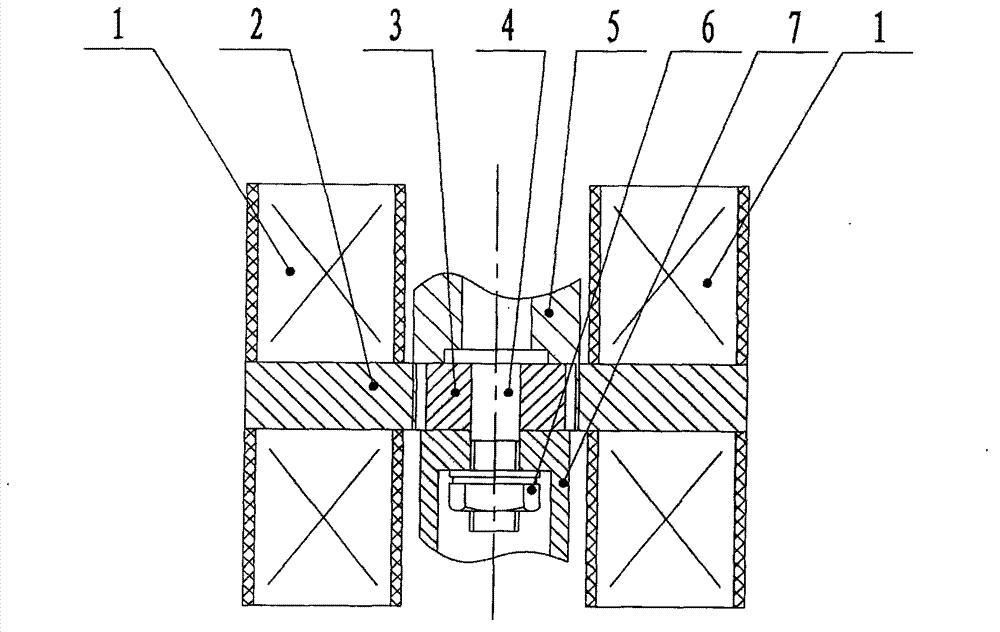
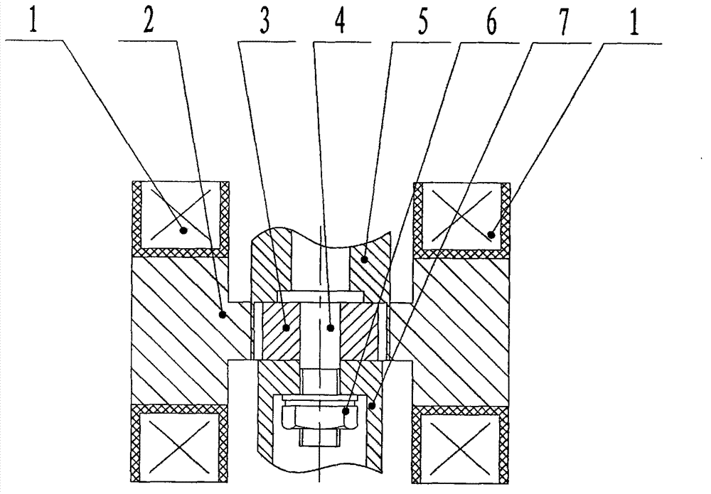
[0026] like figure 1 As shown, it is a schematic structural view of the first embodiment of the electromagnetic rotary reciprocating device in the present invention, the device of this embodiment includes:

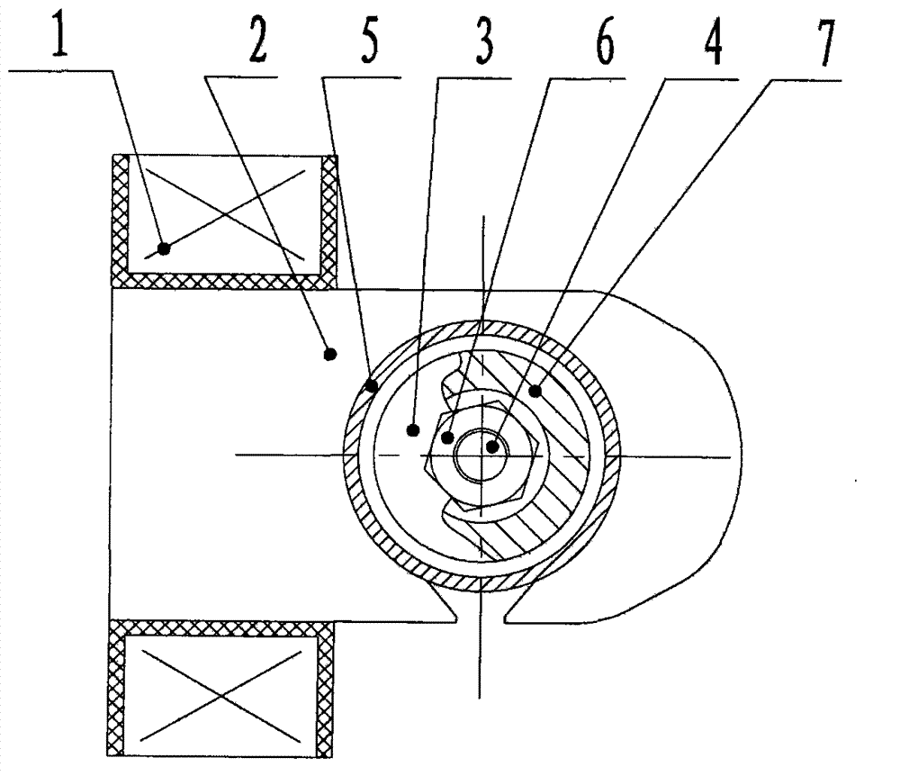
[0027] The first component includes an iron core 2 and a coil 1 , and the two ends of the iron core 2 are respectively wound with the coil 1 .

[0028] The second component includes a permanent magnet 3 and a connecting rod group 4, the permanent magnet 3 runs through the iron core 2, and the permanent magnet 3 is connected with the connecting rod group 4;

[0029] When a forward or reverse pulse current is passed through the coil, an attractive or repulsive fo...


PUM


Abstract

The invention discloses a magneto-electric rotation reciprocating device which comprises a first component and a second component. The first component comprises a core and a coil. The coil is wound on at least one end of the core, and the second component comprises a permanent magnet and a connecting rod group. The permanent magnet is arranged in the core, and a gap exists between the permanent magnet and the core. The permanent magnet is connected with the connecting rod group. When positive or negative pulse current flows in the coil, attracted or repellent acting force is generated between the permanent magnet and the core, and the permanent magnet drives the connecting rod group to rotate. Due to the fact that the permanent magnet is radially magnetized and arranged in the core and the permanent magnet attracts different geometric shaft radiuses of the core, the problem that the coil is heated and burned off is solved.

Description

technical field [0001] The invention belongs to the technical field of low-voltage electrical appliances, in particular to a magnetoelectric rotary reciprocating device. Background technique [0002] At present, the reciprocating devices for magnetoelectric rotation all use the continuous application of current to the coil, and the generated magnetic field drives the iron core to move linearly. A rack is arranged on the connecting rod of the iron core, and a spring is arranged at the other end of the rack. When current is applied to the coil, the iron core pushes the connecting rod and drives the rack to move in one direction, and at the same time drives the gear to rotate. When the current is cut off, the spring releases the compression energy, which drives the iron core, connecting rod, and rack to make a return movement, and at the same time drives the gear to make a reverse rotation movement, thereby forming a reciprocating rotation movement, and driving other components...

Claims


Application Information

Patent Timeline
Patent Type & Authority Applications(China)
IPC IPC(8): H02K33/18
Inventor 刘文华刘焘陈智顺李孝书赵清明李崇辉
Owner 刘文华
Why Eureka
Try Eureka