Dimming circuit and method of LED (Light Emitting Diode) lighting lamp

A technology for LED lighting and dimming circuits, which is applied in the layout of electric lamp circuits, lighting devices, light sources, etc., can solve the problems of many remote controllers, high cost, and time requirements for switching actions, and achieves the effect of strong anti-interference ability.

Active Publication Date: 2013-09-11
GOLDP ELECTRICAL APPLIANCES
View PDF5 Cites 18 Cited by
  • Summary
  • Abstract
  • Description
  • Claims
  • Application Information

AI Technical Summary

Problems solved by technology

The LED lighting control circuit is equipped with a remote control receiving device, and the LED lighting can be dimmed or multi-level dimmed through the remote control. The disadvantage is that one lighting is equipped with a remote control, and there are many remote controls, which is troublesome to manage. The cost is also high
For example, using the NU102 dedicated chip, you can use the switch action of the ordinary wall switch within a specified time to realize the brightness adjustment of the LED lighting; but the existing method can only provide 4 levels of brightness adjustment for the LED lighting, and The switching action has a time requirement

Method used


Image

  • Dimming circuit and method of LED (Light Emitting Diode) lighting lamp
  • Dimming circuit and method of LED (Light Emitting Diode) lighting lamp
  • Dimming circuit and method of LED (Light Emitting Diode) lighting lamp

Examples


Embodiment Construction

[0040] The present invention will be further described in detail below in conjunction with the embodiments and the accompanying drawings, but the embodiments of the present invention are not limited thereto.

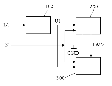
[0041] Such as figure 1 The structure block diagram of the present invention shown is composed of a switch and brightness control signal given unit 100 , a brightness control signal conversion unit 200 , and a brightness adjustment drive unit 300 .

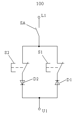
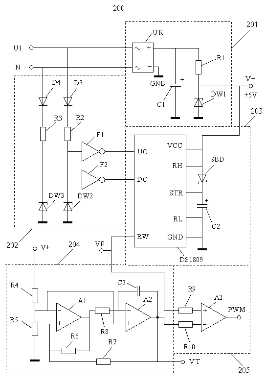
[0042] The switch and brightness control signal given unit 100 is provided with a single live wire input terminal L1 and a single live wire output terminal U1, and the single live wire input terminal L1 is connected to the live wire of an AC power supply; the brightness control signal conversion unit 200 is provided with a live wire input Terminal U1, neutral line input terminal N, PWM brightness control signal output terminal, the live line input terminal U1 is connected to the single live line output terminal U1 of the sin...


PUM


Abstract

A dimming circuit of an LED (Light Emitting Diode) lighting lamp is formed by a switch and brightness control signal given unit, a brightness control signal conversion unit and a brightness adjustment driving unit. According to a dimming method of the LED lighting lamp, a method that positive and negative half waves of an alternating current power supply are controlled to be passed through or not is utilized and a single fire-wire mode is utilized to give a brightness control signal of the LED lighting lamp; the brightness control signal controls a digital potentiometer to output PWM (Pulse Width Modulation) duty ratio modulation voltage; a PWM brightness control signal is generated after the PWM duty ratio modulation voltage is in comparison with a triangular wave signal; and the duty ratio adjustable PWM brightness control signal controls the brightness change of the LED lighting lamp through the brightness adjustment driving unit. The dimming circuit of the LED lighting lamp can achieve replacement and upgrade of the ordinary lighting lamp without remote control, control line or power line re-laying.

Description

technical field [0001] The invention relates to a lighting lamp technology, in particular to a multi-level dimming circuit and method for an LED lighting lamp. Background technique [0002] Due to the non-linear characteristics of the LED lighting lamp, the brightness of the LED lighting lamp cannot be realized by adjusting the voltage. [0003] When a controllable constant current source is used to adjust the brightness of the LED lighting, the change of the working current will cause the color shift of the LED lighting. At the same time, the load current of the LED lighting at low brightness will also become very low, which will make the The efficiency of the constant current source decreases and the temperature rise increases, and the power consumption on the driver chip increases, which will damage the life of the constant current source and the LED light source. [0004] Using PWM (pulse width modulation) dimming method to control the brightness of LED lighting can avo...

Claims


Application Information

Patent Timeline
Patent Type & Authority Applications(China)
IPC IPC(8): H05B37/02
Inventor 凌云肖伸平周维龙
Owner GOLDP ELECTRICAL APPLIANCES
Why Eureka
Try Eureka