
Grinder structure with movable rotating vertical grinding head

A grinding head and vertical grinding technology, which is used in grinding machine parts, manufacturing tools, grinding/polishing equipment, etc., and can solve problems such as occupation, insufficient functionality, and large space.

Active Publication Date: 2016-02-03
林淑芬
View PDF7 Cites 0 Cited by
  • Summary
  • Abstract
  • Description
  • Claims
  • Application Information

AI Technical Summary

Problems solved by technology

[0002] The grinding machine can be said to be one of the most versatile machines at present. It can grind any shape of the structure on the workpiece, such as: planes, slopes, irregular surfaces, grooves...etc.; to adapt to For the needs of various industries, grinding machines are usually made into vertical and horizontal rotating grinding wheels. However, in fact, the functionality is still insufficient. Even various automatic computer-controlled grinding machines can only be used for a specific type of grinding machine. The processing steps are processed. If it is converted into another type of processing, for example, the surface of the work object changes in various inclination angles. In order to achieve a usable state, it is often necessary to add multiple sets of working grinding heads on the grinding machine to cope with the required surface. Grinding, in other words, with the increase in the types of work objects to be processed, it is necessary to invest in additional sets of different types of processing grinding heads on the grinding machine. In this way, it will not only increase the purchase of the overall equipment cost, and the independent setting of each processing grinding head will also make the overall volume of the grinding machine larger, resulting in a situation that takes up a considerable amount of space, which is not in line with the economic principle; in view of the serious defects mentioned above, in today's ideal, practical and progressive , Sincerely waiting for the goal of striving for improvement

Method used


Image

  • Grinder structure with movable rotating vertical grinding head
  • Grinder structure with movable rotating vertical grinding head
  • Grinder structure with movable rotating vertical grinding head

Examples


Embodiment Construction

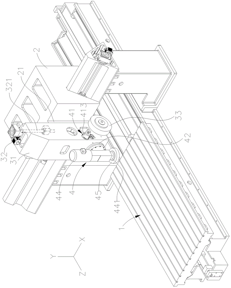
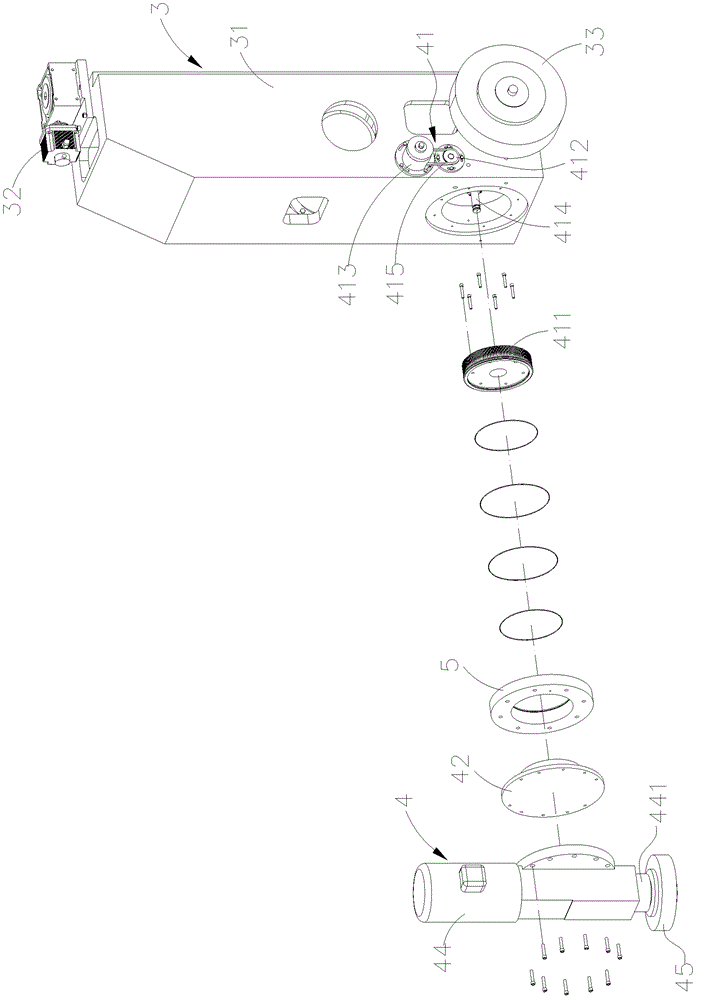
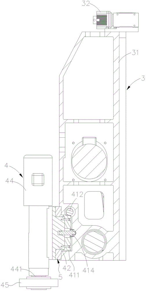
[0035] Such as Figure 1 ~ Figure 4 As shown, the grinding machine structure provided by the embodiment of the present invention has a movable rotating vertical grinding head, which is mainly composed of a machine body 1, a sliding seat 2, a first grinding head group 3 and a second grinding head group 4, etc. combined; of which:

[0036] The structure of the machine body 1 is generally the same as the existing structure and will not be repeated here, and the workpiece can be grinded in the directions of X, Y, and Z axes on it;

[0037] The sliding seat 2 is slidably arranged in the X-axis direction of the body 1, and a sliding groove 21 is formed in the Y-axis direction;

[0038] The first grinding head group 3 is slidably arranged in the chute 21 of the slide seat 2 by a housing 31, that is, a guide rail 311 is formed on the housing 31 (as shown in Figures 1 and 4). The guide rail 311 and the chute 21 are combined in the form of a dovetail groove. Therefore, the first grind...


PUM


Abstract

The invention discloses a grinding machine structure provided with a movable rotary vertical grinding head. A second grinding head group capable of controlling rotation is arranged on a first grinding head group in the Y-axis direction of the conventional grinding machine body; two grinding head groups with different functions are combined together; and the vertical grinding head of the second grinding head group can be driven to rotate by using the motor, and can rotate integrally at an appropriate moment under the driving action of another driving power. Due to such matching and combination, the vertical grinding head of the second grinding head group can be used for rotationally grinding and processing on various slope angle surfaces of workpieces under the driving action of the motor power, so that the grinding function is enhanced, a good grinding effect and a high grinding speed are achieved, and the phenomenon that the conventional grinding machine occupies a large space can be improved effectively.

Description

technical field [0001] The invention relates to a grinding machine structure, in particular to a grinding machine structure with a movable rotating vertical grinding head. Background technique [0002] The grinding machine can be said to be one of the most versatile machines at present. It can grind any shape of the structure on the workpiece, such as: planes, slopes, irregular surfaces, grooves...etc.; to adapt to For the needs of various industries, grinding machines are usually made into vertical and horizontal rotating grinding wheel types. However, in fact, the functionality is still insufficient. Even various automatic computer-controlled grinding machines can only be used for a specific type of grinding machine. The processing steps are processed. If it is changed to another type of processing, for example, the surface of the work object changes in various inclination angles. In order to achieve a usable state, it is often necessary to add multiple sets of working gri...

Claims


Application Information

Patent Timeline
Patent Type & Authority Patents(China)
IPC IPC(8): B24B41/04
Inventor 林淑芬
Owner 林淑芬
Learn More