High-speed rotor positioning link structure

A technology of coupling structure and high-speed rotor, applied in couplings, rigid shaft couplings, portable lifting devices, etc., can solve problems such as easy loosening and failure, and achieve the effect of ensuring radial positioning

Active Publication Date: 2013-09-18
CHINA AVIATION POWER MACHINE INST
View PDF5 Cites 8 Cited by
  • Summary
  • Abstract
  • Description
  • Claims
  • Application Information

AI Technical Summary

Problems solved by technology

[0003] The purpose of the present invention is to provide a new type of high-speed rotor positioning connection structure to solve the problem that the single-bond or double-bond static co

Method used


Image

  • High-speed rotor positioning link structure
  • High-speed rotor positioning link structure
  • High-speed rotor positioning link structure

Examples


Example Embodiment

[0019] The embodiments of the present invention will be described in detail below with reference to the accompanying drawings, but the present invention can be implemented in a variety of different ways defined and covered by the claims.

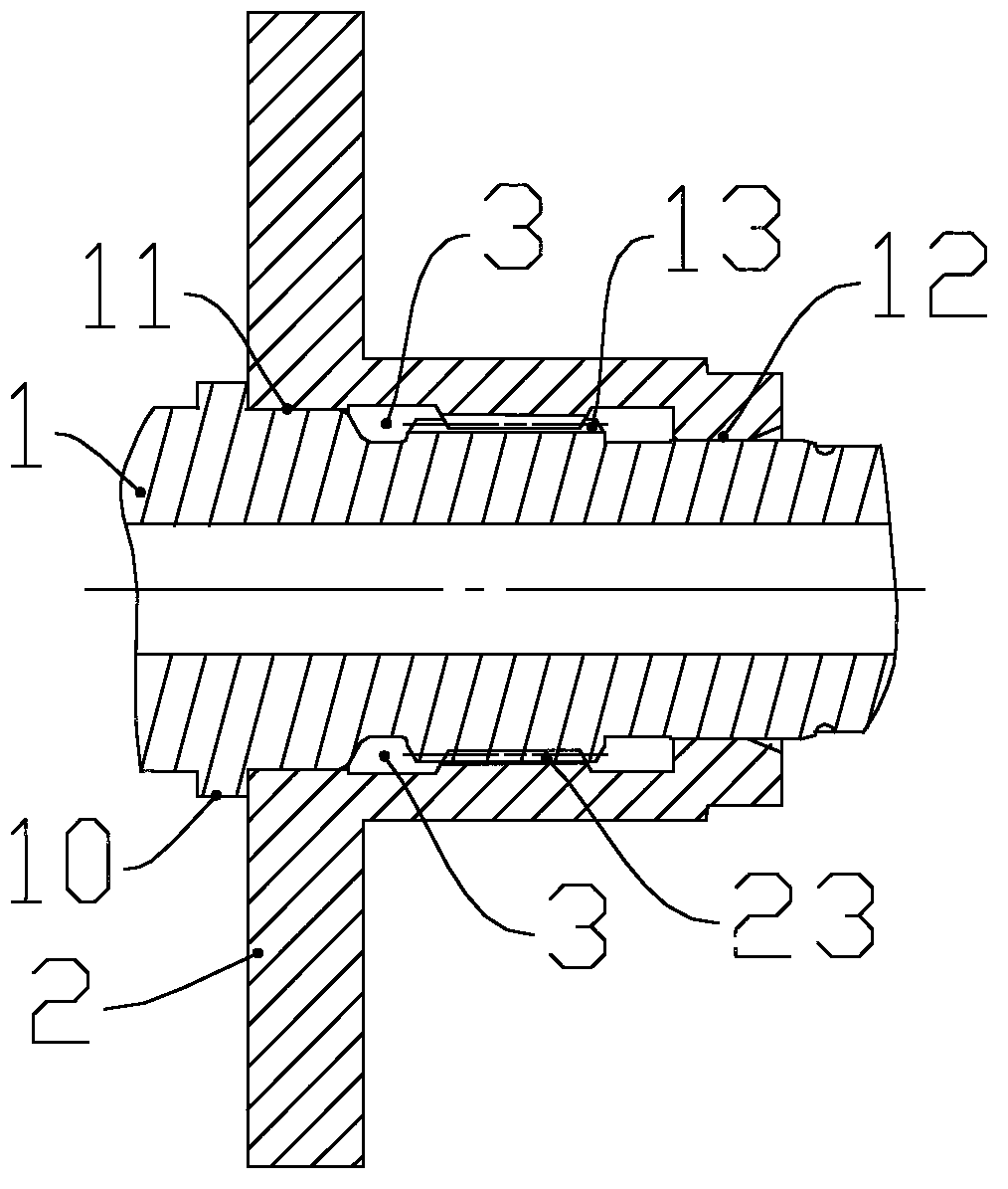
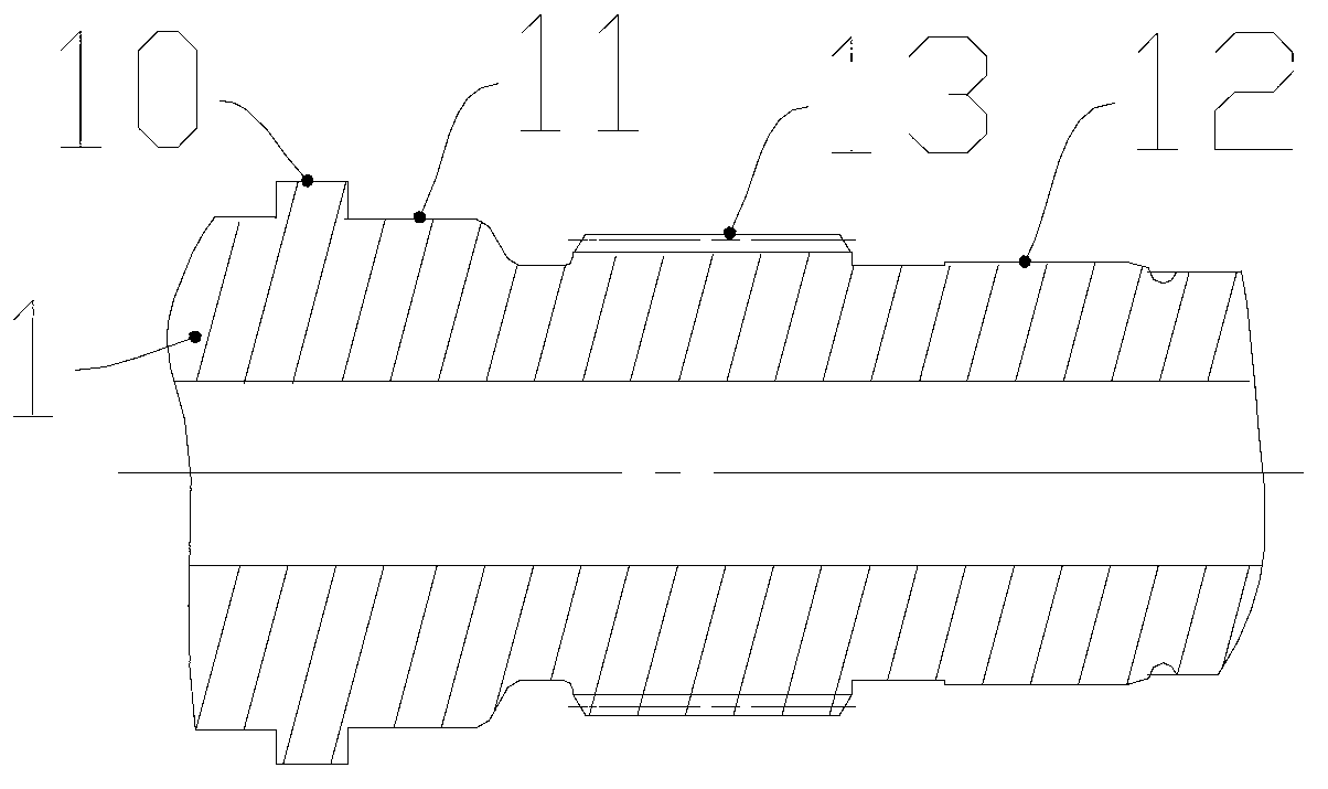
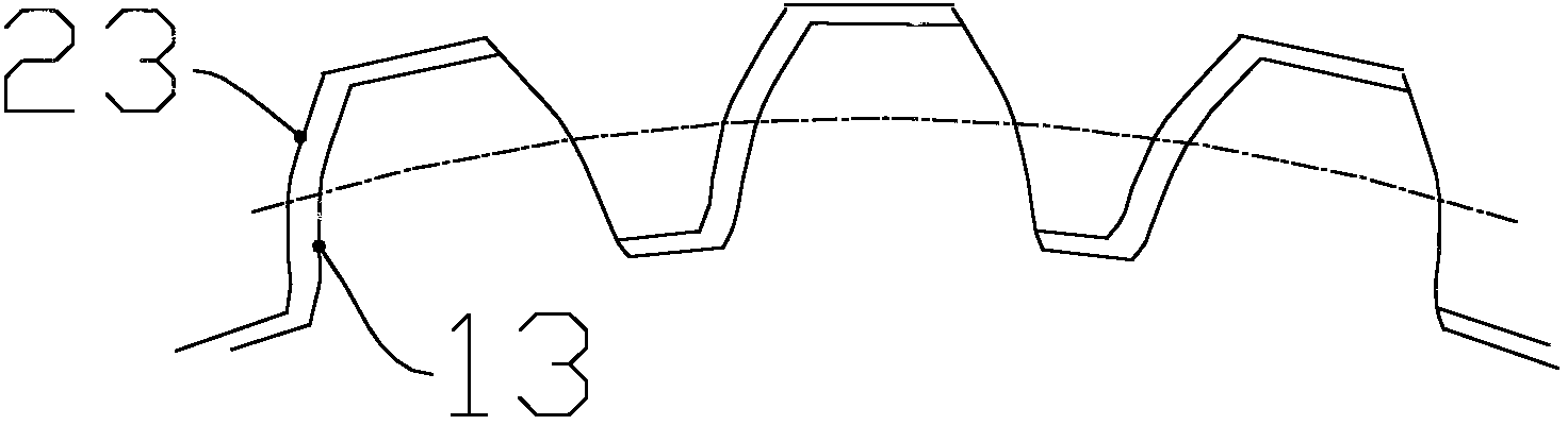
[0020] See figure 1 The present invention provides a high-speed rotor positioning and coupling structure, which includes a rotor shaft 1 and a rotor 2 sleeved on the periphery of the rotor shaft 1. The outer diameter of the rotor shaft 1 includes a first end 11 and a second end 12 opposite to the first end 11. The outer diameter of the rotor shaft 1 and the inner diameter of the rotor 2 pass through the first end 11 and the second end 12. Fit connection; the outer diameter of the rotor shaft 1 is provided with an external gear 13, and the inner diameter of the rotor 2 is oppositely provided with an internal gear 23, and the internal gear 23 and the external gear 13 are internally meshed. The combined structure of interference fit and gear inter...


PUM

PropertyMeasurementUnit
Thicknessaaaaaaaaaa
Modulusaaaaaaaaaa

Abstract

The invention provides a high-speed rotor positioning link structure which comprises a rotor spindle and a rotor, wherein the rotor spindle is sleeved with the rotor on the periphery of the rotor spindle; the external diameter of the rotor spindle comprises a first end and a second end arranged in a position opposite to that of the first end; the external diameter of the rotor spindle is in interference fit connection with the internal diameter of the rotor at the first end and the second end; external gears are arranged on the external diameter of the rotor spindle; internal gears are arranged on the internal diameter of the rotor in an opposite manner; the external gears are in internal gearing with the internal gears. The high-speed rotor positioning link structure has the following benefits: a combined structure formed by the interference fit connection and the internal gearing of the gears can better ensure the radial positioning of the rotor spindle and the rotor, and the reliability and capability of bearing impulse load of the rotor spindle and the rotor during a high-speed high-temperature high-load operating process.

Description

Technical field [0001] The invention relates to the field of aeroengines, in particular to a high-speed rotor positioning and coupling structure. Background technique [0002] There are many high-speed rotating connection mechanisms in the structure of aero-engines, and these rotating mechanisms are required to have high rotation accuracy, high stability and a certain torque transmission function. In the prior art, a single-key or double-key static connection structure is usually adopted. Its rotation accuracy is not high, and the torsion load is small, and it cannot meet the requirements of aeroengines for high speed, high temperature and high load. This structure only uses interference fit to transmit by friction. The twisted structure, if the rotating mechanism is impacted when working in a high-temperature environment, its interference fit is likely to loosen and fail, which will directly affect the rotation accuracy of the shafting and reduce the reliability and service life...

Claims


Application Information

Patent Timeline
IPC IPC(8): F16D1/10F16H55/17
Inventor 陈冰
Owner CHINA AVIATION POWER MACHINE INST
Why Eureka
Try Eureka