A method and system for determining the sampling time of infrared data

A technology of sampling time and infrared data, applied in the field of infrared positioning, can solve the problems of inability to judge touch events, reduce the positioning accuracy and sensitivity of infrared touch screens, etc., achieve the effects of improving positioning accuracy and sensitivity, wide application range, and low cost

Inactive Publication Date: 2016-05-25
GUANGDONG VTRON TECH CO LTD
View PDF4 Cites 0 Cited by
  • Summary
  • Abstract
  • Description
  • Claims
  • Application Information

AI Technical Summary

Problems solved by technology

When the infrared receiving tube that has entered the supersaturated state is blocked, it is likely that a large part of the infrared light is blocked by the infrared receiving tube, but since the infrared receiving tube is still in a saturated state at this time, the collected data is still not blocked The data at that time is the same, so the microcomputer system cannot judge the touch event at this time according to the data collected by the infrared receiving tube, which will greatly reduce the positioning accuracy and sensitivity of the infrared touch screen

Method used


Image

  • A method and system for determining the sampling time of infrared data
  • A method and system for determining the sampling time of infrared data
  • A method and system for determining the sampling time of infrared data

Examples


Embodiment 1

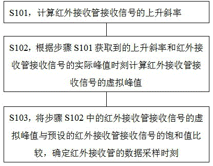
[0027] Such as figure 1 As shown, it is a flowchart of a specific embodiment of a method for determining an infrared data sampling time according to the present invention. See figure 1 , A method for determining the time of infrared data sampling in this specific embodiment includes the following steps:

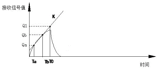
[0028] S101: Calculate the rising slope of the signal received by the infrared receiving tube; among them, when the infrared receiving tube receives the signal, a series of received signals will be obtained, and the value of the received signal has an upward trend and a downward trend. By obtaining the receiving signal in an upward trend The slope formed between the values ​​is used as the rising slope.

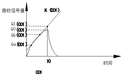
[0029] S102: Calculate the virtual peak value of the signal received by the infrared receiving tube according to the rising slope obtained in step S101 and the actual peak time of the signal received by the infrared receiving tube; there is a peak sampling time in the curve forme...

Embodiment 2

[0047] Such as Figure 5 Shown is a schematic diagram of the results of a specific embodiment of a system for determining the sampling time of infrared data according to the present invention. See Figure 5 The system for determining the sampling time of infrared data in this specific embodiment specifically includes:

[0048] The slope acquisition module 11 is used to calculate the rising slope of the curve corresponding to the rising trend of the infrared receiving tube receiving signal value; among them, the infrared receiving tube will obtain a series of receiving signals when receiving the signal, and there is an upward trend between the received signal values. In the downward trend, the slope obtaining module 11 obtains the slope formed between the received signal values ​​in the upward trend as the rising slope.

[0049] The peak calculation module 12 is used to calculate the virtual peak value of the signal received by the infrared receiving tube according to the acquired...

Embodiment approach

[0055] As a preferred embodiment, the data sampling time determining module 13 includes:

[0056] The difference acquisition module is used to make the difference between the virtual peak value of the received signal of the infrared receiving tube and the preset saturation value of the received signal of the infrared receiving tube to obtain the difference; Setting, it can be set to the highest working voltage parameter of the infrared receiver tube. This highest working voltage parameter can be queried from the infrared receiver tube’s specifications or manuals, etc., or it can be set according to the actual situation. In the mode, the received signal value of the infrared receiver tube read at the actual peak time in the non-touch state is taken as the saturation value of the infrared receiver tube.

[0057] The result judgment module is used to judge whether the difference is greater than the preset threshold, and if so, it is determined that the data sampling time of the infrar...


PUM


Abstract

The invention relates to the technical field of infrared positioning, and more particularly to a method and system for determining the sampling time of infrared data. The method comprises the following steps: calculating the rising slope of the signal received by the infrared receiving tube; calculating the virtual peak value of the signal received by the infrared receiving tube according to the rising slope and the actual peak moment of the signal received by the infrared receiving tube; combining the virtual peak value of the signal received by the infrared receiving tube with the Comparing the saturation value of the signal received by the preset infrared receiving tube to determine the data sampling time of the infrared receiving tube. The present invention can effectively prevent the infrared receiving tube from collecting data at the time of oversaturation of the received signal, thus effectively avoiding the situation that the received signal collected when the light emitted by the infrared receiving tube is still saturated, and at the same time ensures that it does not enter into oversaturation The receiving sensitivity of the infrared receiving tube in the state can improve the positioning accuracy and sensitivity of the infrared positioning device.

Description

Technical field [0001] The present invention relates to the field of infrared positioning technology, and more specifically, to a method and system for determining the time of infrared data sampling. Background technique [0002] Infrared touch screen has the advantages of simple structure, high stability, high resolution, convenient installation, etc., and is not interfered by current, voltage and static electricity, and is suitable for working under certain harsh environmental conditions. This makes infrared touch screens proliferate and become more and more touch screens. Mainstream products in the market. Its basic structure is to install several pairs of infrared emitting tubes and infrared receiving tubes in a certain order on the periphery of a display surface. These infrared emitting tubes and infrared receiving tubes form a transmitting and receiving pair in a one-to-one correspondence, forming a mutually perpendicular transmitting and receiving array along the edge of ...

Claims


Application Information

Patent Timeline
Patent Type & Authority Patents(China)
IPC IPC(8): G06F3/042
Inventor 李军明钟杰婷
Owner GUANGDONG VTRON TECH CO LTD
Why Eureka
Try Eureka