Eureka AIR delivers breakthrough ideas for toughest innovation challenges, trusted by R&D personnel around the world.

A wireless passive two-way laser communication module

A laser communication, wireless passive technology, applied in the directions of optical fiber radio, optical fiber transmission, electromagnetic transceivers, etc., can solve the problems of being susceptible to interference, low security of WIFI communication, relatively high environmental requirements, and improve stability and reliability. , the effect of improving communication stability

Active Publication Date: 2022-05-10
ZHONGBEI UNIV
View PDF0 Cites 0 Cited by
  • Summary
  • Abstract
  • Description
  • Claims
  • Application Information

AI Technical Summary

Problems solved by technology

[0002] At present, the development of various special equipment requires a large number of tests to verify its functionality and reliability, and to effectively improve product quality. However, it is difficult to obtain equipment parameters through wired methods during the test process. At the same time, there is strong electromagnetic interference in the test environment. Wireless communication is carried out through traditional Bluetooth, WIFI, LORA, Zigbee, etc. At the same time, in order to obtain higher acquisition accuracy and sampling frequency, a higher transmission bit rate is required. Except for WIFI, the other bit rates of traditional wireless transmission are very low. However, WIFI communication is less secure and susceptible to interference, and the peripheral design components are complex
In addition, in some complex application environments, communication devices cannot be powered by wired means, and wireless power supply or batteries are required.
Batteries have natural use defects, and the environmental requirements are relatively high. Temperature and pressure will affect their life and use.
Therefore, the communication modules in the prior art cannot reliably acquire signals in environments such as strong electromagnetic interference, high rotation, and high temperature.

Method used


Image

  • A wireless passive two-way laser communication module
  • A wireless passive two-way laser communication module
  • A wireless passive two-way laser communication module

Examples


experiment example

[0057] Experimental example: the laser distance is l=12mm, and the detector diameter is d=1.2mm. L=100-2.7 (relative position of the laser)-3 (relative position of the detector)=94.3mm, the number of simulated rays is 100 for each laser, and the number of analysis rays is 100,000. The parameter of the laser light source is 35mW, the half divergence angle is 8°, and the The sensitivity is -69.6dBm (estimated in the manual), and finally according to the ZEMAX simulation, the received optical power of the detector is 0.64mW (about -2dBm), such as Figure 10 shown. Calculated by formula (2)|δ| =10.6mm.

[0058] When the Y direction of the single-sided laser module is 18mm, the received optical power is 0.0232mW (about -16.3dBm), such as Figure 11 shown. Far greater than the detection sensitivity of the detector, meeting the design requirements. When the X-direction offset of the single-sided laser module is 10.6mm, the received optical power is 0.0351mW (about -14.5dBm), such...


PUM


Abstract

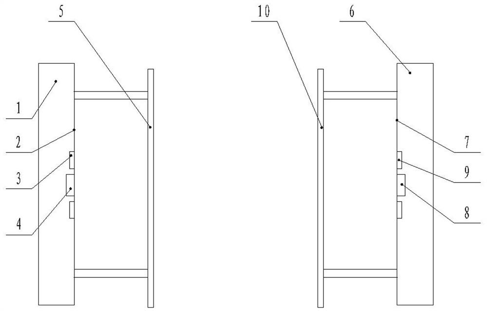
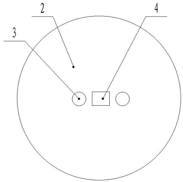
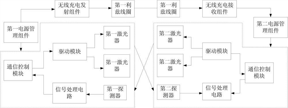
The invention belongs to the technical field of industrial communication, and discloses a wireless passive two-way laser communication module, which includes a first laser communication unit and a second laser communication unit used as a pair, the first laser communication unit includes a first base plate, and the center of the first base plate A first detector is fixedly arranged, and a first laser is respectively arranged and fixed on both sides of the first detector; A second laser is respectively arranged and fixed on the side; the first laser and the second laser are used to send out a laser signal carrying a coded signal, and the detector and the second detector are used to respectively receive the laser emitted by the second laser and the first laser; the present invention Not only can laser wireless two-way communication be realized, but also the stability of communication signals can be improved.

Description

technical field [0001] The invention belongs to the technical field of industrial communication, and specifically relates to a small wireless passive two-way laser communication module, which can be used in working conditions such as strong electromagnetic interference, high rotation, passive power supply, and signal transmission control with confidentiality requirements. Background technique [0002] At present, the development of various special equipment requires a large number of tests to verify its functionality and reliability, and to effectively improve product quality. However, it is difficult to obtain equipment parameters through wired methods during the test process. At the same time, there is strong electromagnetic interference in the test environment. Wireless communication is carried out through traditional Bluetooth, WIFI, LORA, Zigbee, etc. At the same time, in order to obtain higher acquisition accuracy and sampling frequency, a higher transmission bit rate i...

Claims


Application Information

Patent Timeline
Patent Type & Authority Patents(China)
IPC IPC(8): H04B10/073H04B10/079H04B10/2575H04B10/40
CPCH04B10/073H04B10/0795H04B10/07955H04B10/2575H04B10/40
Inventor 庞俊奇熊继军谭秋林
Owner ZHONGBEI UNIV
Why Eureka
Eureka Blog
Learn More