Support controller for electrohydraulic control system

An electro-hydraulic control system and bracket controller technology, which is applied in mine roof brackets, mining equipment, earthwork drilling, etc., can solve the problem of slow communication speed of single-line CAN bus, limitation of the maximum number of nodes of CAN bus, and influence on the normal operation of control units, etc. problems, to achieve the effect of meeting the requirements of automatic control functions, enhancing anti-interference ability, and improving resource utilization

Active Publication Date: 2013-09-25
TIANJIN HUANING ELECTRONICS
View PDF5 Cites 3 Cited by
  • Summary
  • Abstract
  • Description
  • Claims
  • Application Information

AI Technical Summary

Problems solved by technology

[0003] The existing mine hydraulic support electro-hydraulic control system generally uses a single power supply to supply power to the control unit and external equipment such as solenoid valves and sensors. The problem with the design of the single power supply is: if the power supply system Failure of external devices such as solenoid valves or sensors will seriously affect the normal operation of the control unit; at the same time, the single-channel power supply design limits the load capacity of the power module
[0004] In addition, most of the existing mine hydraulic support electro-hydraulic control systems use a mining hydraulic support controller composed of a single-line CAN bus. The CAN communication protocol standard is not set for the coal mining industry. The existing problems are: CAN The bus usually has a limit on the maximum number of nodes, and the single-line CAN bus has a slow communication rate and poor anti-interference ability

Method used


Image

  • Support controller for electrohydraulic control system
  • Support controller for electrohydraulic control system

Examples


Embodiment Construction

[0019] Embodiments of the present invention will be described in further detail below in conjunction with the accompanying drawings.

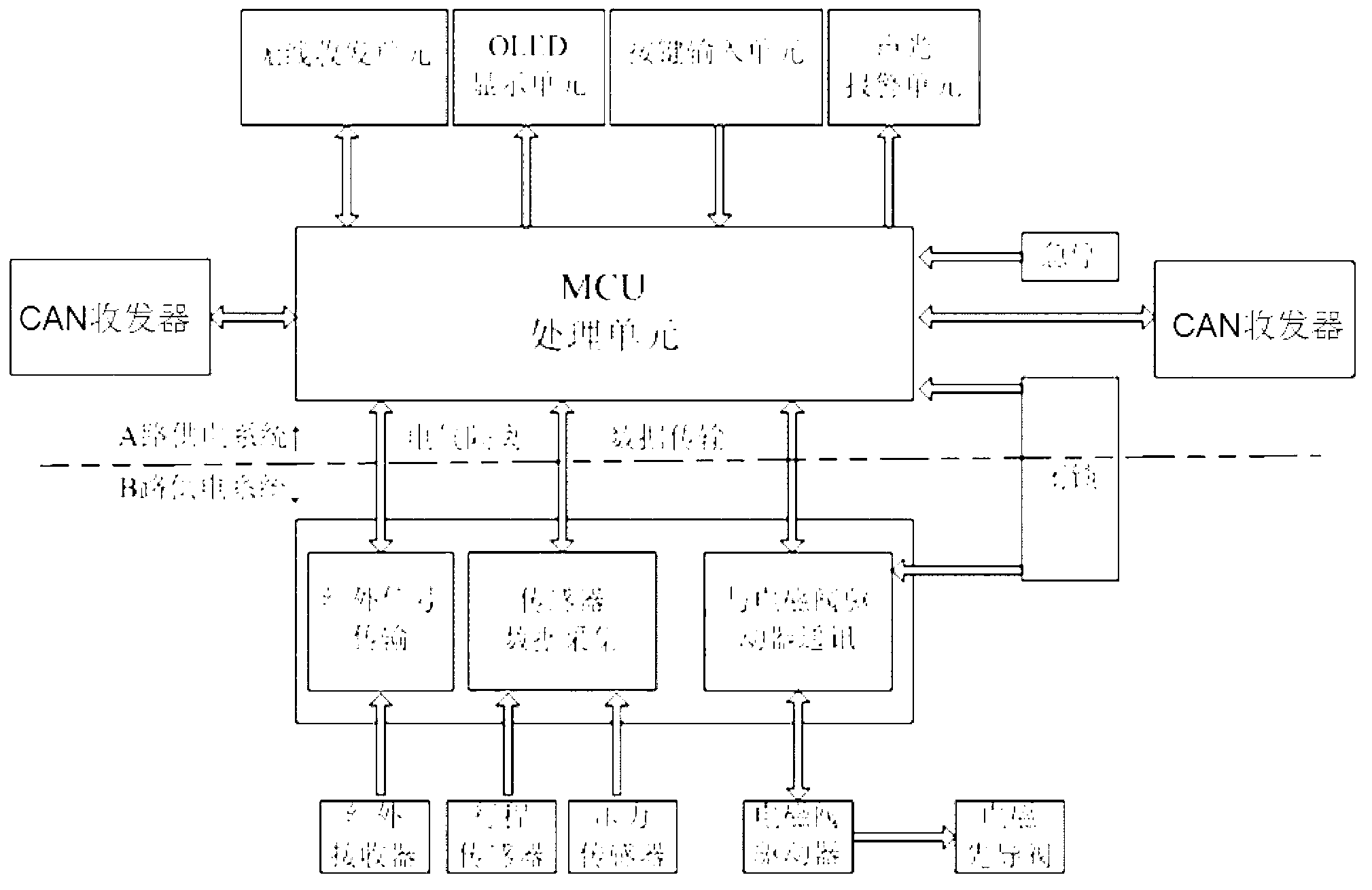
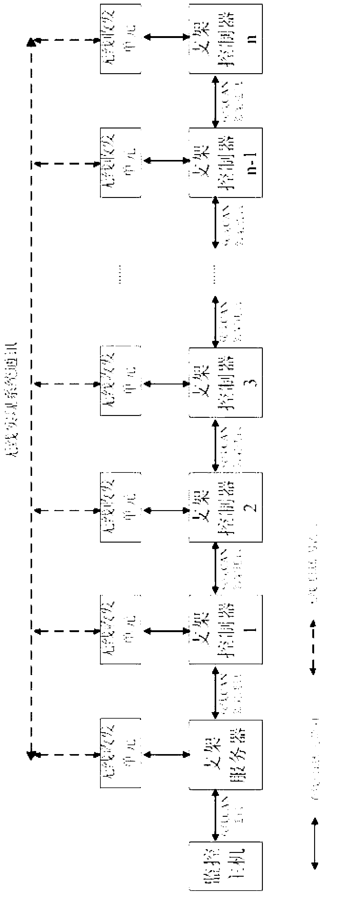
[0020] A bracket controller for electro-hydraulic control systems such as figure 1 As shown, it includes MCU processing unit, wireless transceiver unit, human-computer interaction unit, two CAN transceivers, data acquisition unit, solenoid valve driver, emergency stop locking unit and two-way power supply system. The MCU processing unit is respectively connected with the wireless transceiver unit, two CAN transceivers, the human-computer interaction unit and the emergency stop locking unit. The bracket controller realizes the mutual communication function of adjacent bracket controllers through two CAN transceivers. The wireless transceiver unit Use ZigBee or WiFi module to realize system data transmission function. The MCU processing unit is respectively connected with the wireless transceiver unit, the infrared receiver and the solenoid valv...


PUM


Abstract

The invention relates to a support controller for an electrohydraulic control system. The support controller is mainly characterized by comprising an MCU processing unit, a wireless transceiving unit and two paths of power supply systems. The MCU processing unit is respectively connected with the wireless transceiving unit, two CAN transceivers, a human-machine interaction unit, a data acquisition unit, an infrared receiver and a magnetic valve driver, and the magnetic valve driver is connected with a magnetic pilot valve; one path of power supply system is connected with and supplies power to the MCU processing unit, the wireless transceiving unit, the two CAN transceivers and the human-machine interaction unit; the other path of power supply system is connected with and supplies power to the infrared receiver, the data acquisition unit, the magnetic valve driver and the magnetic pilot valve. The support controller for the electrohydraulic control system is reasonable in design, data transmission is carried out in a wireless transmission mode and in a manner that the two paths of power supply systems are adopted, automatic control function demands of a hydraulic support are met, the resource utilization ratio of the support controller is improved, the use of auxiliary equipment is reduced, and failure rates are lowered.

Description

technical field [0001] The invention belongs to the technical field of electro-hydraulic control, in particular to a bracket controller for an electro-hydraulic control system. Background technique [0002] In fully mechanized underground mining, in order to improve production efficiency and meet the needs of operational safety, the action of the support should be adapted to the equipment capacity of the working face and the efficiency of the production process, so as to ensure that the coal shearer can quickly advance and cut coal. It is not only necessary to improve the support control operation To increase the degree of automation, the convenience, reliability and safety of control must be further improved. The electro-hydraulic control will speed up the action speed of the bracket, improve the degree of automation, reduce the workload of operation, improve efficiency and enhance safety. [0003] The existing mine hydraulic support electro-hydraulic control system genera...

Claims


Application Information

Patent Timeline
IPC IPC(8): E21D23/12
Inventor 薛红伟孙建辉张敏杰田东升李寒涛张远
Owner TIANJIN HUANING ELECTRONICS
Why Eureka
Try Eureka