Extendable-length encapsulating housing arrangement for an encapsulated electrical energy transmission device

A technology for enclosing housings and power transmission equipment, which is applied in the installation of switchgear, mechanical equipment, busbars, etc., and can solve the problems of wear and tear of plastic guide rings.

Active Publication Date: 2013-10-02
SIEMENS ENERGY GLOBAL GMBH CO & KG
View PDF6 Cites 3 Cited by
  • Summary
  • Abstract
  • Description
  • Claims
  • Application Information

AI Technical Summary

Problems solved by technology

Plastic guide rings th

Method used


Image

  • Extendable-length encapsulating housing arrangement for an encapsulated electrical energy transmission device
  • Extendable-length encapsulating housing arrangement for an encapsulated electrical energy transmission device

Examples


Embodiment Construction

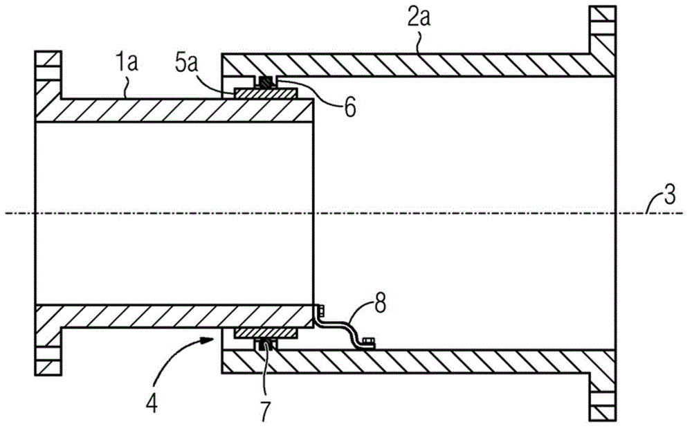
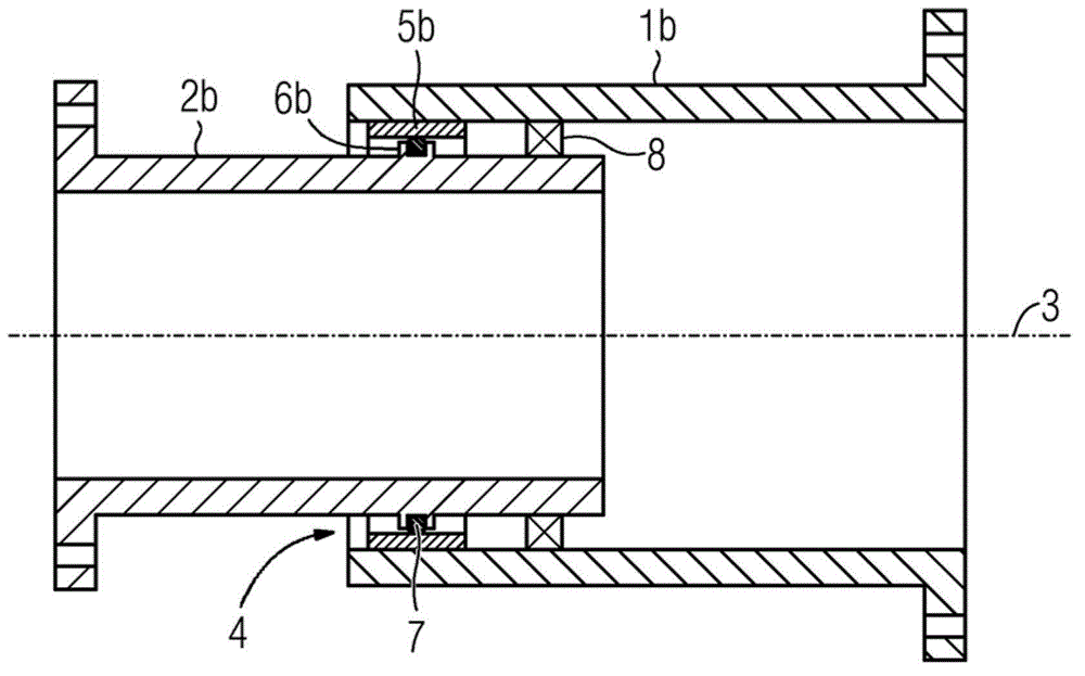
[0027] figure 1 The first closure housing arrangement shown in has a first closure housing 1 a and a second closure housing 2 a. The enclosing housings 1 a , 2 a are tubular and oriented coaxially to the main axis 3 . The cross section of the first closure shell 1 a is selected in such a way that the first closure shell 1 a is surrounded by the second closure shell 2 a to form the seam 4 . The two closure housings 1 a , 2 a are movable relative to each other along the main axis 3 , so that the length of the first closure housing arrangement in the direction of the main axis 3 varies.

[0028] At the end facing away from the seam 4, the closure housings 1a, 2a are each designed with an annular flange. The closure housings 1a, 2a can be connected to other components via said annular flange. The ends facing away from one another can also be closed in a fluid-tight manner, so that a fluid can be contained within the first closed housing arrangement. Thus, for example, sealing ...


PUM


Abstract

An extendable-length encapsulating housing arrangement has a first and a second encapsulating housing (1a, 1b, 2a, 2b). The first encapsulating housing (1a, 1b) has a sliding face (5a, 5b), against which the second encapsulating housing (2a, 2b) bears.

Description

technical field [0001] The invention relates to a variable length enclosure housing arrangement for enclosed power transmission equipment, comprising a first enclosure housing with a sliding surface and a second enclosure housing which is slidably supported on The sliding surface of the first closed shell. Background technique [0002] A closed housing arrangement of this type is known, for example, from laid-open document DE 26 03 040 A1. A closed housing arrangement is described there, which has a first and a second closed housing. The known closure housings are each designed tubularly and telescopically inserted into one another. Provision is made for the relative movement between the closure housings to use plastic guide rings as sliding bodies. It is also proposed that one of the closure housings is formed from an elastic material, so that changes in length are compensated for by deformation of the elastic material. As a result, although sliding movements are avoide...

Claims


Application Information

Patent Timeline
IPC IPC(8): H02B13/045H02G5/00
CPCH02B13/005H02B13/045H02G5/002F16L27/12H02G3/0462
Inventor S.劳坦伯格M.施米特克
Owner SIEMENS ENERGY GLOBAL GMBH CO & KG
Why Eureka
Try Eureka