
Cable connection device and method

A cable connection and cable technology, applied in the direction of cable joints, etc., can solve the problems of air gap breakdown, easy generation of air gap, long installation time, etc., to reduce the possibility of breakdown voltage, reduce the generation of air gap, and shorten the installation time the effect of time

Inactive Publication Date: 2015-01-28
中科英华长春高技术有限公司
View PDF5 Cites 4 Cited by
  • Summary
  • Abstract
  • Description
  • Claims
  • Application Information

AI Technical Summary

Problems solved by technology

[0003] The above-mentioned connection method has some disadvantages and deficiencies: the installation time is too long, and when the cable body is installed, an air gap is easily generated between the winding layer and the cable body, and an air gap is also easily generated between layers of winding various tape materials. The surface after winding cannot be guaranteed to be uniform, and the surface often has unevenness
In addition, the insulation cut-off between the tape material and the cable body cannot be completely overlapped. After the cable is bent, the wound tape material will be compressed and deformed, resulting in a larger air gap on the contact surface.
[0004] The air gap generated during the above installation process will bring hidden dangers to the safe operation of the cable. The breakdown voltage strength of the air gap of 3kV / mm is far smaller than the breakdown voltage strength of the insulation layer and the accessory insulation layer of 25kV / mm; during the operation of the cable The middle air gap is prone to partial discharge and then partial breakdown and the formation of a discharge path. During long-term operation, electrical trees and discharge along the surface will be formed, until the cable or accessories break down, resulting in operational accidents

Method used


Image

  • Cable connection device and method
  • Cable connection device and method
  • Cable connection device and method

Examples


Embodiment Construction

[0028] The core of the present invention is to provide a cable connection device, which can eliminate the air gap generated when connecting cables in the prior art, thereby avoiding the formation of electric trees, discharge along the surface and even breakdown, and greatly improve the cable operation. level of security. Another core of the present invention is to provide a cable connection method capable of achieving the above technical effects.

[0029] In order to enable those skilled in the art to better understand the solution of the present invention, the technical solution of the present invention will be further described in detail below in conjunction with the drawings and specific embodiments.

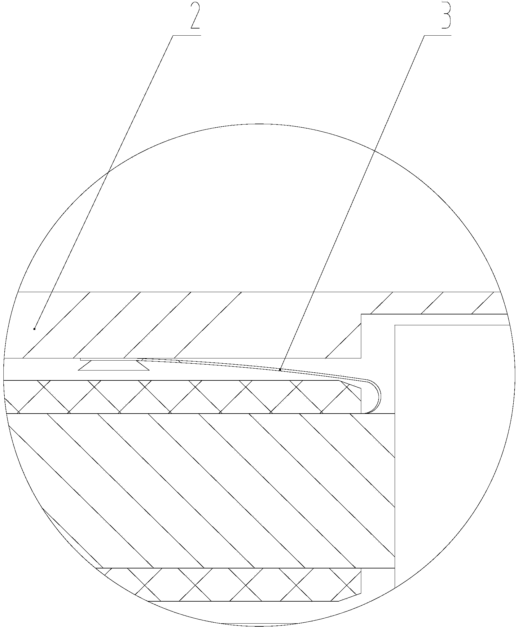
[0030] Please refer to figure 1 , is a structural schematic diagram of a specific embodiment of the cable connection device provided by the present invention.

[0031] In a specific embodiment, the cable connection device provided by the present invention has a connecting p...


PUM


Abstract

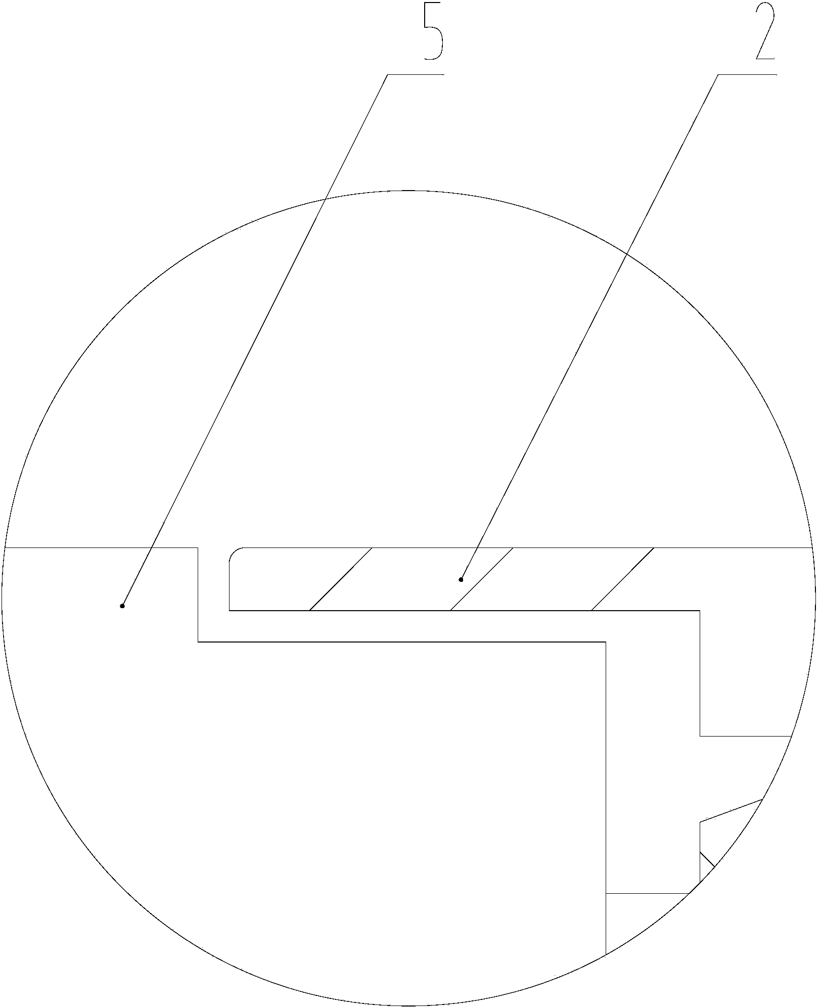
The invention discloses a cable connection device. The cable connection device comprises a connection pipe (1), and further comprises a shielding case (2) and a voltage equalizing wire (3), wherein the shielding case covers the connection pipe (1) and makes contact with insulation layers (5) of cables, and the two ends of the voltage equalizing wire are connected with cable conductors (4) and the shielding case (2) respectively. The metal shielding case is arranged to replace the prior mode that cables are fixed in the connection mode of winding of a semiconductive belt or combination of winding of a semiconductive belt and waterproof filling glue, and air gaps are not easily generated in the connection and use process. The voltage equalizing wire is arranged to be connected with the cable conductors and the inner sides of the shielding case, so that the electric potential at the cable conductors and the electric potential at the shielding case are the same, the discharging phenomenon caused by the gradient difference of the electric potentials is avoided, and safety is improved. The invention further provides a connection method of the cable connection device.

Description

technical field [0001] The invention relates to the technical field of electrical equipment, in particular to a cable connection device. In addition, the invention also relates to a cable connection method. Background technique [0002] High-voltage transmission cables are essential equipment for high-voltage transmission. In the process of erecting high-voltage transmission lines, it is often necessary to connect two different transmission cables. Commonly used methods for connecting power transmission cables are to pre-treat the power transmission cables first, crimp the connecting tube, and then wrap the semi-conductive tape on the surface of the crimped connecting tube, or wrap the semi-conductive tape and waterproof filling glue, so that the wound after winding The surface is flush with the insulation layer of the cable, and then other steps such as the installation of the intermediate joint body are performed. [0003] The above-mentioned connection method has some d...

Claims


Application Information

Patent Timeline
Patent Type & Authority Applications(China)
IPC IPC(8): H02G15/18
CPCH02G15/18
Inventor 李小军徐义全陈德财
Owner 中科英华长春高技术有限公司
Learn More