Multi-frequency antenna system applicable to mobile terminal with metal frame structure

A mobile terminal, multi-frequency antenna technology, applied to antenna equipment with additional functions, antennas, antenna supports/installation devices, etc. The effect of many, small occupied space and wide bandwidth

Active Publication Date: 2013-10-09
SHANGHAI AMPHENOL AIRWAVE COMM ELECTRONICS CO LTD
View PDF8 Cites 87 Cited by
  • Summary
  • Abstract
  • Description
  • Claims
  • Application Information

AI Technical Summary

Problems solved by technology

In addition, due to the complexity of functions such as mobile phone terminals, the space for mobile phone antennas is getting smaller and smaller. Therefore, based on the premise of being responsible for the small space in the environment, debugging an antenna covering

Method used


Image

  • Multi-frequency antenna system applicable to mobile terminal with metal frame structure
  • Multi-frequency antenna system applicable to mobile terminal with metal frame structure
  • Multi-frequency antenna system applicable to mobile terminal with metal frame structure

Examples


Embodiment 1

[0036] It is applicable to the multi-frequency antenna system of mobile terminal with metal frame structure, including metal frame, PCB board and antenna part; PCB board is a general printed circuit board (Printed circuit board).

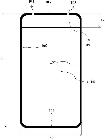
[0037] like figure 1 As shown, the metal frame includes a top frame 102, a bottom frame 103, a first side frame 106 and a second side frame 107, and the top frame 102, the first side frame 106, the bottom frame 103 and the second side frame 107 enclose a first A space, a first gap 104 is defined between one end of the bottom frame 103 and one end of the first side frame 106 , and a second gap 105 is defined between the other end of the bottom frame 103 and one end of the second side frame 107 . The metal frame is wrapped around the mobile terminal; the top frame 102 corresponds to the top of the mobile terminal, the bottom frame 103 corresponds to the bottom of the mobile terminal, and the first side frame 106 and the second side frame 107 correspon...

Embodiment 2

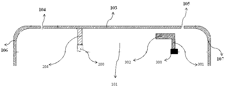
[0056] like Figure 7 As shown, the difference between this embodiment and Embodiment 1 is that: the feeder part also includes a site 201, and the feeder routing part also includes a second feeder branch 210; one end of the second feeder branch 210 is connected to the site 201, and the first The other end of the second feed branch 210 is connected to an end of the first feed branch 204 close to the feed source 200 .

[0057] In this embodiment, the feeding part adopts the form of IFA. Compared with the T-shaped wiring method using a monopole antenna (MONOPOLE) in Embodiment 1, the working principle and effect of this embodiment are the same as those in Embodiment 1. Basically the same, except that the second feed branch 210 and the location 201 in this embodiment are omitted in Embodiment 1, and the length of the wiring is slightly shorter than that of this embodiment, which can further compress the space occupied by the antenna. This embodiment can As an alternative to Embod...

Embodiment 3

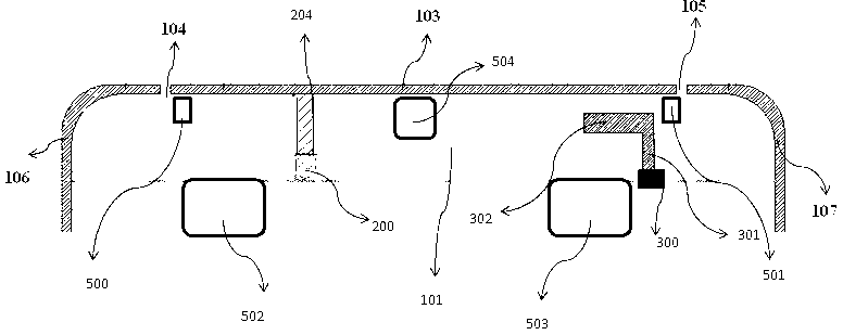
[0060] like Figure 8 As shown, the difference between this embodiment and Embodiment 1 is that the first low-frequency coupling arm 301 and the second low-frequency coupling arm 302 are both arranged above the clearance area 101 , and are located in the same plane as the feeder trace.

[0061] The working principle and technical effects of this embodiment are basically the same as those of Embodiment 1. The positions of the first low-frequency coupling arm 301 and the second low-frequency coupling arm 302 can be adjusted according to the surrounding environment. If the first low-frequency coupling arm 302 in Embodiment 1 When other components of the mobile terminal need to be arranged at the corresponding positions of the low frequency coupling arm 301 and the second low frequency coupling arm 302 in the clearance area 101 , the solution of this embodiment can be adopted. The positions of the first low frequency coupling arm 301 and the second low frequency coupling arm 302 a...


PUM


Abstract

The invention discloses a multi-frequency antenna system applicable to a mobile terminal with a metal frame structure. The multi-frequency antenna system comprises a metal frame, a PCB and an antenna part. The metal frame is designed to be part of an antenna radiation body, two gaps are formed in the bottom portion of the metal frame, a feeding wiring part and the metal frame together form a T-shaped monopole antenna or an IFA antenna so that the metal frame itself can be used for producing low frequency and high frequency resonance, and other coupling parts can be additionally arranged to be used for adjusting the low frequency and high frequency resonance according to the needs of working frequency bands. The multi-frequency antenna system has the advantages that due to the fact that the gaps of the metal frame are formed in the bottom portion, a user can be prevented from touching the gaps during the actual use process, and the phenomenon that the performance of the antenna is poor when the antenna is held by a hand is avoided; the working frequency bands of the multi-frequency antenna system are 704Mhz-960Mhz and 1710Mhz-2700Mhz, and multi-frequency broadband is realized; compared with a traditional general antenna, the multi-frequency antenna system is multiple in frequency band and broad in frequency width; the antenna structure of the multi-frequency antenna system is small in occupied space, and mutual influence cannot be generated between the antenna structure and surrounding environments.

Description

technical field [0001] The invention belongs to the technical field of antennas, and in particular relates to a multi-frequency antenna system suitable for a mobile terminal with a metal frame structure. Background technique [0002] Mobile terminal antenna multi-frequency broadband has always been the development direction of mobile communication, especially for portable mobile terminals. Universal Mobile Telecommunications System (UMTS) is the current mainstream, and its frequency bandwidth is 824Mhz-960Mhz and 1710Mhz-2170Mhz. On the other hand, with the application of LTE technology, in addition to the above frequency bands, LTE700MHZ is also included, so the bandwidth of low frequency is 700Mhz-960Mhz. Some also include high-band LTE2.3GHZ and LTE2.5GHZ, so the high-frequency bandwidth is 2500Mhz-2700Mhz. In addition, due to the complexity of functions such as mobile phone terminals, the space for mobile phone antennas is getting smaller and smaller. Therefore, based o...

Claims


Application Information

Patent Timeline
IPC IPC(8): H01Q1/44H01Q5/01H01Q1/22H01Q5/10
Inventor 董孩李
Owner SHANGHAI AMPHENOL AIRWAVE COMM ELECTRONICS CO LTD
Why Eureka
Try Eureka