Eureka AIR delivers breakthrough ideas for toughest innovation challenges, trusted by R&D personnel around the world.

One-way energy-dissipation supporting component

An energy-dissipating support and one-way technology, which is applied to building components, earthquake resistance, etc., can solve the problems of reduced bearing capacity, stiffness degradation, energy dissipation capacity degradation, etc., and achieve the effect of reducing axial pressure

Inactive Publication Date: 2015-04-15
HUNAN UNIV
View PDF8 Cites 0 Cited by
  • Summary
  • Abstract
  • Description
  • Claims
  • Application Information

AI Technical Summary

Problems solved by technology

However, for the plastic design idea of ​​structural yielding, the dissipation of the energy input into the building structure by earthquakes and wind disasters also means the damage of the structure itself, which creates a problem: to restore the resistance level of the structure before the damage occurs, all Replacement or reinforcement of damaged components may result in huge maintenance costs, and in some cases it will become inoperable; in addition, if the maintenance of the building structure affects the use of the building, it will have a greater impact on public psychology. The impact of the impact caused the public to doubt the safety of the building
Under the action of horizontal reciprocating loads such as earthquakes or strong winds, the frame-supported structure must bear repeated tensile and compressive axial forces. After compression buckling, its bearing capacity decreases, its stiffness degrades, and its energy dissipation capacity degrades accordingly, resulting in the inability to provide stable energy dissipation capacity during the entire earthquake or wind disaster; the compression buckling damage of supporting members will also increase the maintenance cost after the disaster

Method used


Image

  • One-way energy-dissipation supporting component
  • One-way energy-dissipation supporting component
  • One-way energy-dissipation supporting component

Examples


Embodiment Construction

[0019] The present invention will be further described below in conjunction with the accompanying drawings and embodiments.

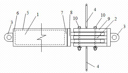
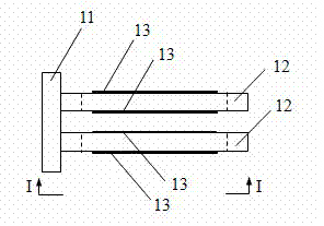
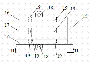
[0020] refer to Figure 1-5 , this embodiment includes a main support rod 1, a one-way energy dissipation member 2, an end connecting ear plate 3, and a tie rod 4; the main support rod 1 is composed of a metal pipe 5, a sealing plate 6 at one end, and a sealing plate 7 at the other end Welding structure; the one-way energy consumption part 2 is composed of Π-type connectors 8, E The Π-type connector 9 and the bolt connection pair 10 are composed of a first end plate 11, two parallel steel plates 12, and a friction element 13 (made of viscoelastic material) attached to the surface of the two parallel steel plates 12. , the first end plate 11 is welded to two parallel steel plates 12, the two parallel steel plates 12 are provided with waist-shaped bolt holes 14, allowing the bolt connection pair 10 to slide in the holes, the E Type connector 9 is welded...


PUM


Abstract

A one-way energy-dissipation supporting component comprises a main supporting rod, a one-way energy-dissipation part, end-portion connecting lug plates and pulling rods. The one-way energy-dissipation part is composed of an n-shaped connecting part, an E-shaped connecting component and a bolt connecting pair. The n-shaped connecting component is composed of a first end plate, two parallel plates and friction elements pasted on the surface of the two parallel plates. The first end plate is connected with the two parallel plates, and a kidney-shaped bolt hole is formed in each parallel plate. The E-shaped connecting plates are composed of a second end plate, two parallel clamping plates and a middle plate, wherein the second end plate is connected with the two parallel clamping plate and the middle plate, side surface connecting lug plates are arranged on the two parallel clamping plates, and bolt holes are formed in the two parallel clamping plates and the middle plate. The n-shaped connecting component and the E-shaped connecting component are connected into a whole through the bolt connecting pair. The one-way energy-dissipation component is connected with the main supporting rod. The pull rods are perpendicularly connected with the two parallel clamping plates through the side surface connecting lug plates. The one-way energy-dissipation supporting component has stable and good energy-consumption capacity in earthquakes or wind damage, can avoid buckling damage due to pressing, and can reduce after-calamity maintenance cost.

Description

technical field [0001] The invention relates to a supporting member in the construction field, in particular to a one-way energy-dissipating supporting member. Background technique [0002] In order to improve the bearing capacity and lateral stiffness of the frame structure, increase the construction height of the structure, and avoid excessively increasing the beam-column section and the corresponding steel consumption, the frame structure is based on a certain number of supports arranged along the height of the structure. The frame-bracing structure is an economical and effective lateral force-resisting structural system. The existing building structure design is mainly the traditional linear elastic design. In order to safely and effectively resist strong earthquakes and strong winds, and reduce the peak load of earthquakes and wind disasters on the building structure, there is also a plastic design idea that turns the structure to yield. However, for the plastic design...

Claims


Application Information

Patent Timeline
Patent Type & Authority Patents(China)
IPC IPC(8): E04B1/98
Inventor 贺拥军周绪红许红胜
Owner HUNAN UNIV
Why Eureka
Eureka Blog
Learn More